Nanofibers, and apparatus and methods for fabricating nanofibers by reactive electrospinning

a technology of reactive electrospinning and nanofibers, which is applied in the field of nanofibers, can solve the problems of difficult fiber formation of highly crosslinked polymers and hyperbranched polymers, ineffective and costly traditional methods, and achieve the effect of expanding the application of electrospinning

Active Publication Date: 2007-01-25
BOARD OF SUPERVISORS OF LOUISIANA STATE UNIV & AGRI & MECHANICAL COLLEGE
View PDF10 Cites 165 Cited by
  • Summary
  • Abstract
  • Description
  • Claims
  • Application Information

AI Technical Summary

Benefits of technology

[0030] The combination of some or all of these aspects of the invention offers significant advantages over prior processes and nanofibers. This invention will significantly expand the applications of electrospinning. It allows the production of nanofibers of cross-linked polymers, as well as non-polymeric materials such as gel nanofibers of ceramic precursors.

Problems solved by technology

However, fabrication of nanofibers is very challenging due to their minute diameters.
Traditional methods, such as formation in porous solids or at the step-edges of laminated crystals, are often ineffective and costly.
However, highly cross-linked polymers and hyperbranched polymers are generally difficult to form as fibers through prior techniques, and even more difficult to form into nanofibers, because they typically have low solubility, and they typically will not melt without undergoing heat-induced decomposition, due to the strong intermolecular bonding or entanglement of the polymer molecules and the formation of polymer networks.
Because the composite gel fibers produced by these processes have contained high levels of organic polymers (typically, about 30% to 66% PVA or PVP), removal of the polymer by calcination has left substantial voids in the final ceramic nanofibers, voids that cannot be healed by calcination or sintering.
However, they are not well-suited for use as reinforcing elements due to their poor mechanical properties.
However, such materials have had low fracture toughness.
Current commercially available zirconia fibers are too thick for such applications (5˜10 μm), because their resulting composites are highly opaque.
Nor have there been prior reports of any method for the direct fabrication of dense ceramic nanofibers through precursor gel nanofibers by electrospinning, without the incorporation of a significant amount of organic polymer.

Method used


Image

  • Nanofibers, and apparatus and methods for fabricating nanofibers by reactive electrospinning
  • Nanofibers, and apparatus and methods for fabricating nanofibers by reactive electrospinning
  • Nanofibers, and apparatus and methods for fabricating nanofibers by reactive electrospinning

Examples


example 1

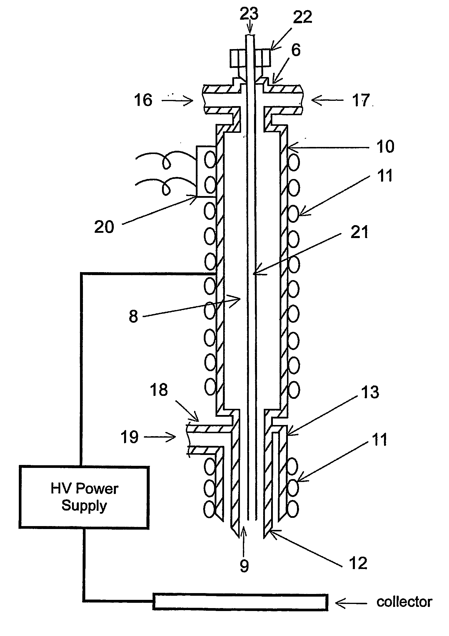
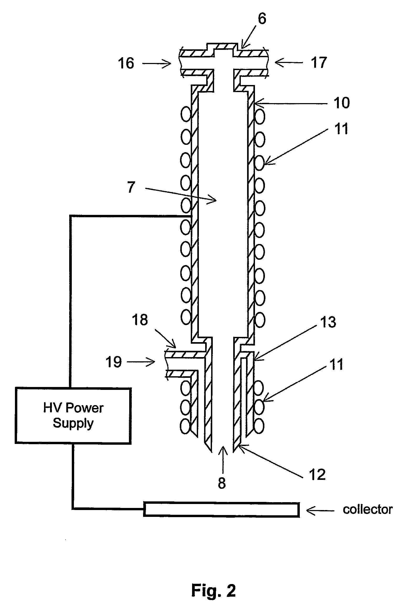
[0054]FIG. 2 depicts an embodiment of a reactive nozzle for chemical reactive electrospinning. It comprises an in-line mixer 6, an in-line chemical reactor 10, one or more coil heaters 11, an electrospinning capillary 12, and a sheath gas tube 13. The reactants are separately introduced though ports 16 and 17, and are mixed in mixer 6. The mixture 7 undergoes chemical reaction in the heated in-line reactor 10 and commences electrospinning at outlet 8 of capillary 12 with the assistance of sheath gas 19, which is introduced through port 18. The total in-line reaction time is

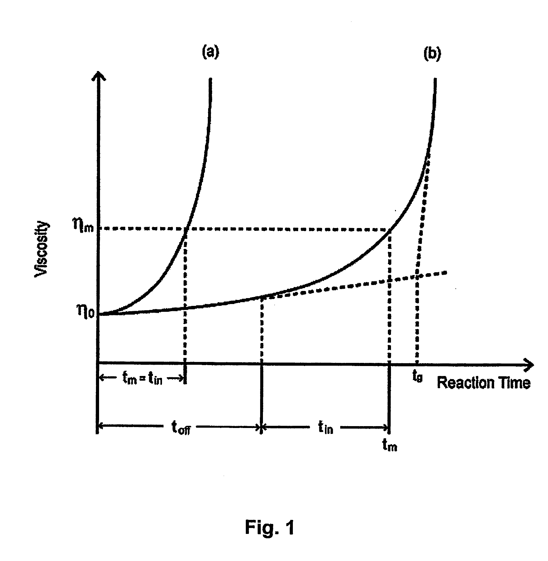
tin=(V1+V2+V3) / F  (3)

or

tin=π(L1d12+L2d22+L3d32) / (4F)  (4)

where tin is the total in-line reaction time (min.); V1, V2, and V3 are the volumes (ml) of the mixer, the reactor, and the capillary, respectively; L1, L2 and L3 are length (mm) of the mixer, the reactor, and the capillary, respectively; d1, d2, and d3 are the inner diameters (mm) of the mixer, the reactor, and the capillary, respectively; and F is the...

example 2

[0056] In another embodiment of the reactive nozzle, shown in FIG. 3, an ultrasonic transducer 20 is attached to mixer 6.

example 3

[0057] In another embodiment of a reactive nozzle (FIG. 4), a separate in-line mixer 6 with an ultrasonic transducer 20 attached is connected to the inlet port 15 of the reactor through a flexible tubing. This configuration allows the use of a high efficiency commercial mixer such as is commonly used in chromatography. Connecting the mixer 6 to the reactor 10 through flexible tubing can help reduce potential adverse effects of sonication on the electrospinning process, while maximizing its benefits. The flexible tubing makes it easier to control both processes. In such a case, the “L1” parameter should include the length of connecting tubing.


PUM

PropertyMeasurementUnit
diameteraaaaaaaaaa
diameteraaaaaaaaaa
diameteraaaaaaaaaa

Abstract

Apparatus and methods for fabricating nanofibers by reactive electrospinning are described. An electrospinning process is coupled with an in-line reactor where chemical or photochemical reactions take place. This invention expands the application of the electrospinning and allows the production of nanofibers of crosslinked polymers and other new materials, such as gel nanofibers of ceramic precursors.

Description

[0001] The benefit of the 05 Sep. 2003 filing date of U.S. provisional patent application Ser. No. 60 / 500,591 is claimed under 35 U.S.C. § 119(e) in the United States, and is claimed under applicable treaties and conventions in all countries.TECHNICAL FIELD [0002] This invention pertains to nanofibers, and to apparatus and methods for producing nanofibers through the in-line coupling of electrospinning with chemical reactions, photochemical reactions, or both. BACKGROUND ART [0003] Nanofibers are thin small fibers, with typical diameters ranging from tens to hundreds of nanometers, up to about 1 micrometer. Nanofibers have been formed from polymers, carbon, and ceramic. Nanofibers have attracted great interest because of their extraordinarily high surface area and length-to-width ratio, as well as their unique physical and mechanical properties. Nanofibers are being used in such areas as filtration, fiber-reinforced nanocomposites, wound dressing, drug delivery, artificial organs, m...

Claims


Application Information

Patent Timeline
Patent Type & Authority Applications(United States)
IPC IPC(8): B29C47/00B29C35/14C04B35/622C04B35/624C04B35/628C22B9/02C22B9/04C22B34/12D01D5/00D01D5/26D01F6/14D01F6/36D01F9/08
CPCC04B35/62236D01F9/08C04B35/624C04B35/62625C04B35/6264C04B35/62844C04B2235/3225C04B2235/3244C04B2235/3418C04B2235/441C04B2235/5264C04B2235/9615D01D5/0038D01D5/38D01F6/14D01F6/36C04B35/6225
Inventor XU, XIAOMING
Owner BOARD OF SUPERVISORS OF LOUISIANA STATE UNIV & AGRI & MECHANICAL COLLEGE
Why Eureka
Try Eureka