Current mirror circuit and constant current having the same

a constant current and mirror circuit technology, applied in the direction of electric variable regulation, process and machine control, instruments, etc., can solve the problems of increasing the chip size and manufacturing cost of the ic, increasing the current flowing the resistor, and reducing the chip size of the ic. , to achieve the effect of high mirror ratio, simple configuration and reduced chip size of the i

Inactive Publication Date: 2007-02-08
DENSO CORP
View PDF5 Cites 8 Cited by
  • Summary
  • Abstract
  • Description
  • Claims
  • Application Information

AI Technical Summary

Benefits of technology

[0013] A resistance of the resistor is set such that the resistor current is larger than each of the base currents of the first and second transistors. Further, this approach clamps a potential of the base line to the power line so that a leak current through the first and second transistors can be prevented when no current flows through the current mirror circuit. As a result of this approach, the resistor becomes dominant in the current flowing though the third transistor.
[0014] The current mirror circuit further includes a current compensation circuit that adds a compensation current to an input current flowing through the first transistor. Because an amount of the compensation current is approximately equal to that of the resistor current divided by a current gain of the third transistor, the compensation current compensates the difference between the collector current of the first transistor and the input current to the current mirror circuit. Thus, even when the resistor having relatively low resistance is connected to the base line to prevent the noise and the leak current, the current mirror circuit can have a highly accurate mirror ratio.
[0015] A constant current circuit having the current mirror circuit supplies a constant current to circuits such as overcharge detection circuits each of which is provided to each of secondary cells that are connected in series to form an assembled battery. The overcharge detection circuits are divided into at least two groups. The current mirror circuit includes first current mirror circuits each of which is provided to each of the groups, a reference current output circuit provided to one of the groups, and a second current mirror circuit provided to the other of the groups. Each of the first current mirror circuits supplies a reference current to each of the overcharge detection circuits in each of the group. The reference current output circuit supplies the reference current to the first mirror circuit of the one of the groups. The reference current is supplied to the first mirror circuit of the other of the groups through the second mirror circuit. Thus, because not all the overcharge detection circuits needs to have the reference currant output circuit, the constant current circuit can have simple configuration. Therefore, when the constant current circuit is integrated into an IC, chip size of the IC can be reduced so that manufacturing cost of the IC can be reduced.

Problems solved by technology

If the cell is used outside its specified voltage range, the cell may have significantly reduced cell capacity and produce heat.
Therefore, when the overcharge detection circuits 2 are integrated into a semiconductor integrated circuit (IC), chip size and manufacturing cost of the IC are increased.
However, reduction in resistance of the resistor results in an increase in current flowing the resistor.
Therefore, because the resistance of the resistor cannot be reduced below a certain level, the noise and leakage current cannot be fully prevented.

Method used


Image

  • Current mirror circuit and constant current having the same
  • Current mirror circuit and constant current having the same
  • Current mirror circuit and constant current having the same

Examples


first embodiment

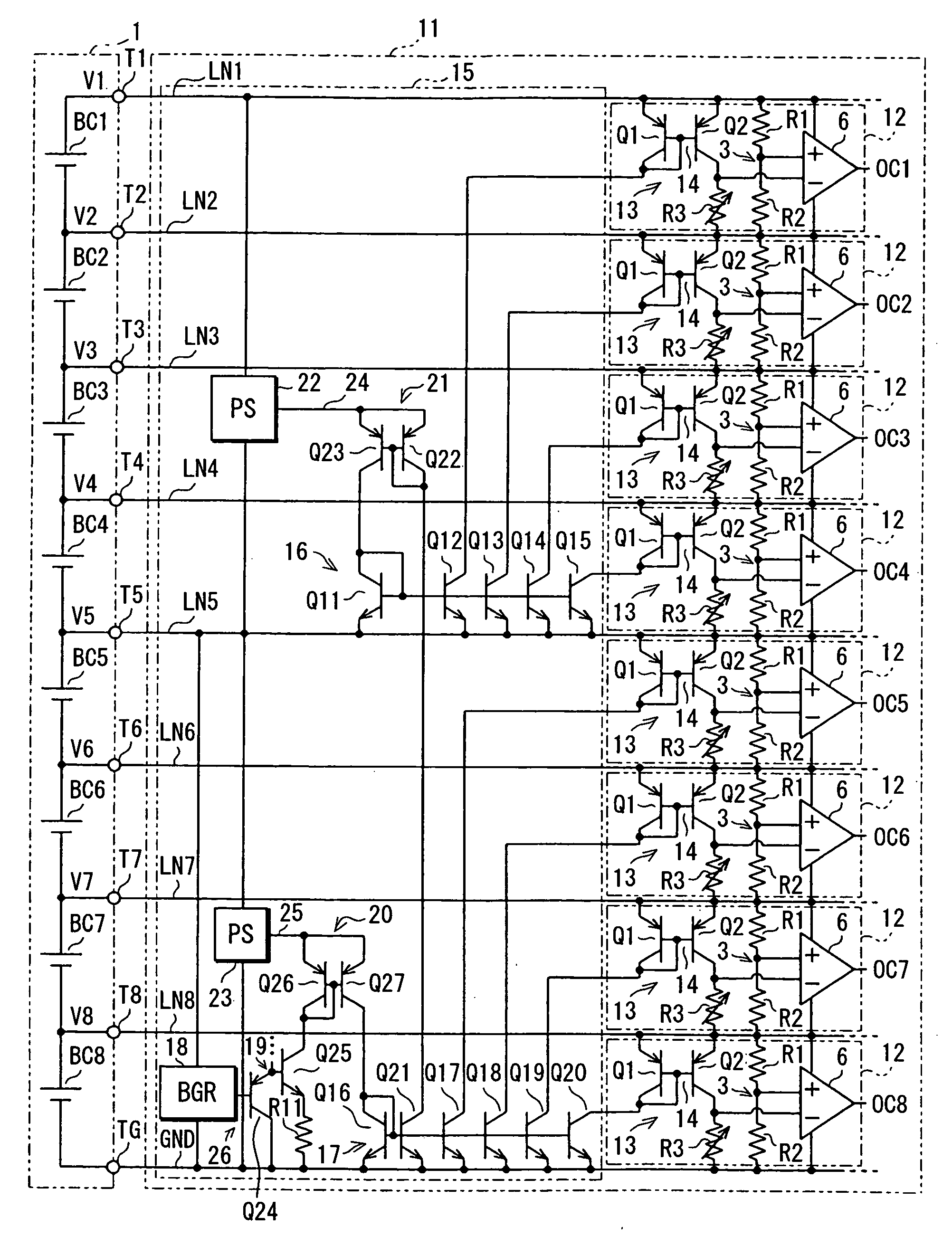
[0027] Referring to FIG. 1, a first embodiment of the present invention is described.

[0028] An assembled battery 1 may be, for example, used for an electric vehicle (EV) and a hybrid vehicle (HV). The assembled battery 1 includes multiple cell groups of secondary cells such as lithium-ion cells (3.6 V per cell). The cell groups are connected in series. Each cell group has eight cells BC1-BC8 that are connected in series. Each cell group has terminals T1-T8, and TG. The terminal TN is a positive terminal of the cell BCN, where N is a positive integer between 1 and 8 inclusive. In other words, the terminal T(M+1) is a negative terminal of the cell BCM, where M is a positive integer between 1 and 7 inclusive. The terminal TG is a negative terminal of the cell BC8.

[0029] A control IC 11 monitors and controls a state of charge (SOC) of the assembled battery 1. Each cell group is provided with the control IC 11. The control IC 11 detects voltages of each of the cells BC1-BC8 and perform...

second embodiment

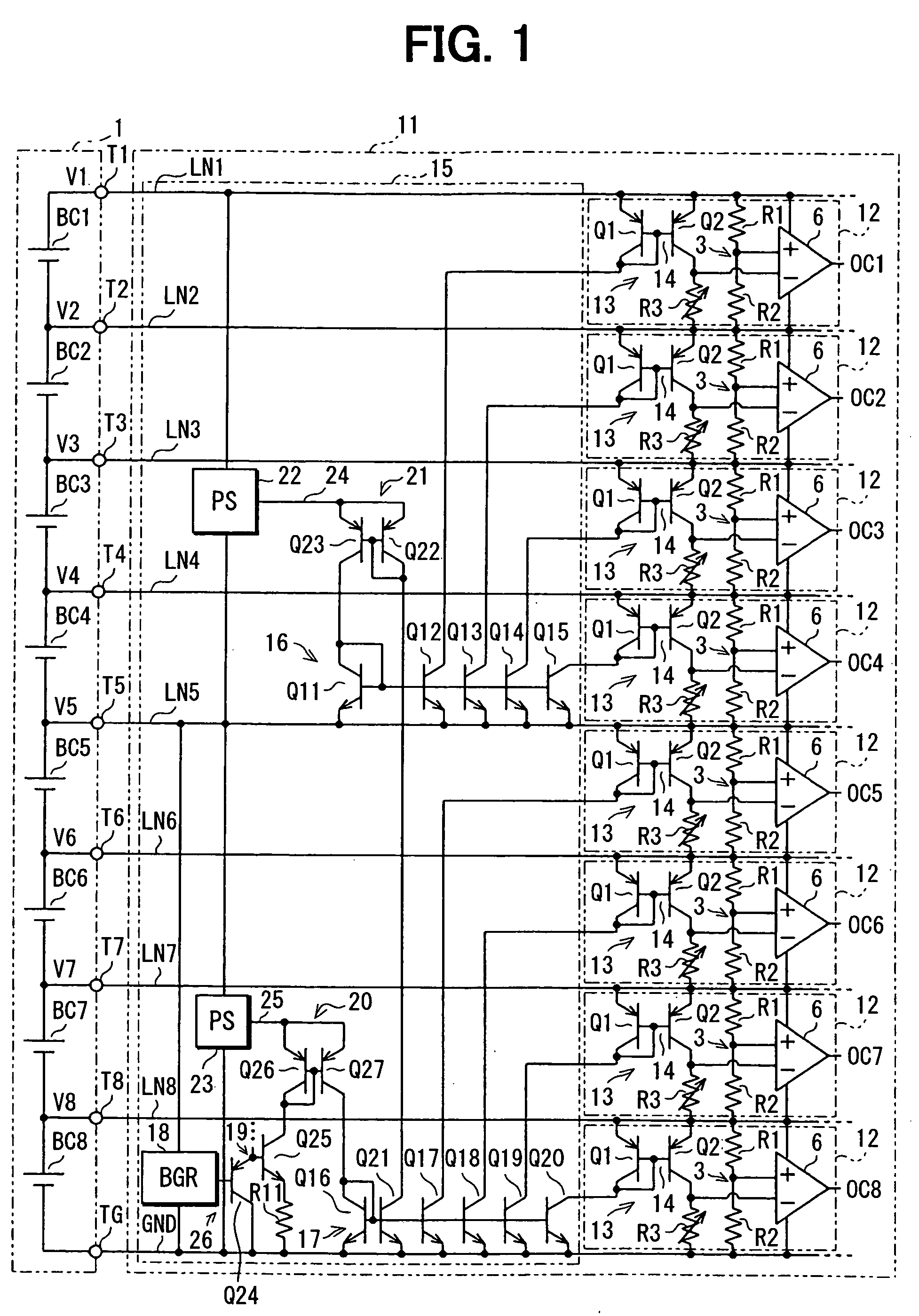
[0054] Referring to FIGS. 2-8, a second embodiment of the present invention is described.

[0055] A control IC 32 monitors and controls the state of charge (SOC) of the assembled battery 1. Each of the cell groups is provided with the control IC 32. The control IC 32 detects the voltage of each of the cells BC1-BC8 and performs the charge / discharge control that keeps the SOC of each of the cells BC1-BC8 in the proper state.

[0056] The control IC 32 includes a constant current circuit 34, an overcharge detection (OCD) circuit 33, and an overdischarge detection circuit (not shown) that is similar in structure to the overcharge detection circuit 33.

[0057] Each of the cells BC1-BC8 is provided with the overcharge detection circuit 33 and the overdischarge detection circuit. When the assembled battery 1 is connected to the control IC 32, the terminals T1-T8 of the assembled battery 1 are connected to voltage lines LN1-LN8 of the control IC 32, respectively. The terminal TG of the assembl...

third embodiment

[0115] Referring to FIG. 9, a third embodiment of the present invention is described. In the third embodiment, each overcharge detection circuit 33 has a current mirror circuit 59 shown in FIG. 9 instead of the current mirror circuit 56. The current mirror circuit 59 is formed by adding an early-effect cancellation circuit 60 to the current mirror circuit 56. The early-effect cancellation circuit 60 includes transistors Q63 (as the sixth transistor), Q64 (as the seventh transistor), and a constant current circuit 61.

[0116] As an example, in the overcharge detection circuit 33 for the cell BC1, the transistor Q63 has the emitter connected to the collector of the transistor Q57 and the collector connected to the trim resistor R41. The transistor Q64 has the emitter connected to the voltage line LN1, the collector connected to the base of the transistor Q63, and the base connected to the collector of the transistor Q57, i.e., the emitter of the transistor Q63. The constant current cir...


PUM


Abstract

A current mirror circuit includes a pair of first and second transistors having bases connected together and emitters connected to a power line, a resistor connected between the bases of the first and second transistors and the power line, a third transistor for providing base currents of the first and second transistors and a resistor current flowing through the resistor, and a current compensation circuit that adds a compensation current to an input current to the first transistor. The amount of the compensation current is approximately equal to that of the resistor current divided by a current gain of the third transistor. Thus, the compensation current compensates the difference between a collector current of the first transistor and the input current.

Description

CROSS REFERENCE TO RELATED APPLICATION [0001] This application is based on and incorporates herein by reference Japanese Patent Applications No. 2005-228094 filed on Aug. 5, 2005 and No. 2005-251314 filed on Aug. 31, 2005. FIELD OF THE INVENTION [0002] The present invention relates to a current mirror circuit and a constant current circuit having the same. BACKGROUND OF THE INVENTION [0003] An assembled battery used for an electric vehicle (EV) and a hybrid vehicle (HV) includes a lot of secondary (i.e., rechargeable) cells connected in series to generate a high voltage ranging from about 100 volts (V) to 400 V. For example, the assembled battery of 300 V is made of 150 lead cells (about 2 V per cell), 250 nickel-hydrogen cells (about 1.2 V per cell), or 80 lithium-ion cells (about 3.6 V per cell) that are connected in series. [0004] The secondary cell, especially, the lithium-ion cell has less resistance to overcharge and overdischarge. If the cell is used outside its specified vol...

Claims


Application Information

Patent Timeline
Patent Type & Authority Applications(United States)
IPC IPC(8): G05F1/10
CPCG05F3/265
Inventor SOBUE, SATOSHIYAMAMOTO, TOMOHISA
Owner DENSO CORP
Why Eureka
Try Eureka