Rare earth - iron - bron based magnet and method for production thereof

a technology of iron-bron and magnets, applied in the field of rare earth-iron-bron based magnets, can solve the problems of degrading the magnetic properties of the magnet surface to a few fractions of those of the inside of the magnet, and achieve the effects of improving the energy product of the magnet, high coercive force, and solving the problem

Inactive Publication Date: 2007-02-15
JAPAN SCI & TECH CORP +1
View PDF3 Cites 96 Cited by
  • Summary
  • Abstract
  • Description
  • Claims
  • Application Information

AI Technical Summary

Benefits of technology

[0041] According to the present invention, a rare earth metal such as Dy, Tb, or the like is deposited on the surface of a rare earth-based magnet and then diffused so that the concentration of the rare earth metal on the surface side is higher than that inside the magnet. Therefore, a high coercive force can be exhibited at a rare earth metal content lower than that of a conventional magnet or the residual magnetic flux density can be improved at a Dy content equivalent to that of a conventional magnet. As a result, the present invention contributes to improvement in the energy product of the magnet and the resolution of the problem with scarce resources such as Dy and the like.

Problems solved by technology

However, a Nd-rich phase in a surface layer of the magnet is damaged by micro grinding cracks and oxidation, and consequently, the magnetic properties of the magnet surface are degraded to a few fractions of those of the inside of the magnet.

Method used


Image

  • Rare earth - iron - bron based magnet and method for production thereof
  • Rare earth - iron - bron based magnet and method for production thereof
  • Rare earth - iron - bron based magnet and method for production thereof

Examples


example 1

[0071] An alloy thin leaf having a thickness of about 0.3 mm was formed from an alloy ingot having the composition, Nd12.5Fe78.5Co1B8, by a strip casting method. Next, this thin leaf was placed in a vessel, and hydrogen gas of 500 Pa was occluded in the thin leaf at room temperature than then released to form a powder of 0.1 to 0.2 mm in size having no regular shape. Then, the powder was ground with a jet mill to prepare a fine powder of about 3 μm.

[0072] Then, 0.05% by mass of calcium stearate was mixed with the fine powder, and the resultant mixture was charged in a mold and molded by pressing in a magnetic field. The resulting molded product was placed in a vacuum furnace and sintered at 1080° C. for 1 hour, and further machined by cutting, boring, cylindrical grinding, and the like to prepare a cylindrical magnet having an outer diameter of 2.4 mm, an inner diameter of 1 mm, a length of 3 mm, and a volume of 11.2 mm3. This magnet was used as comparative example sample (1).

[007...

example 2

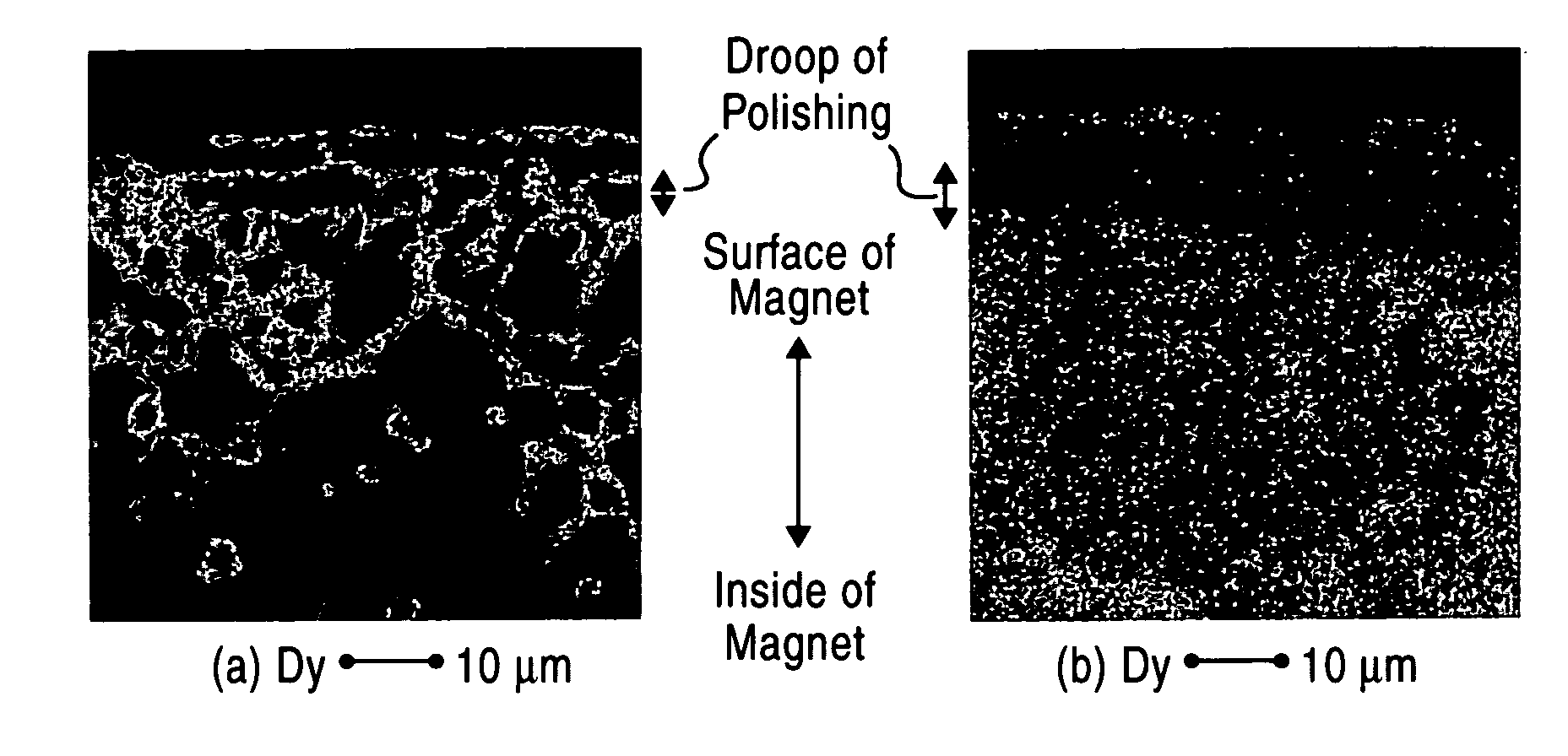
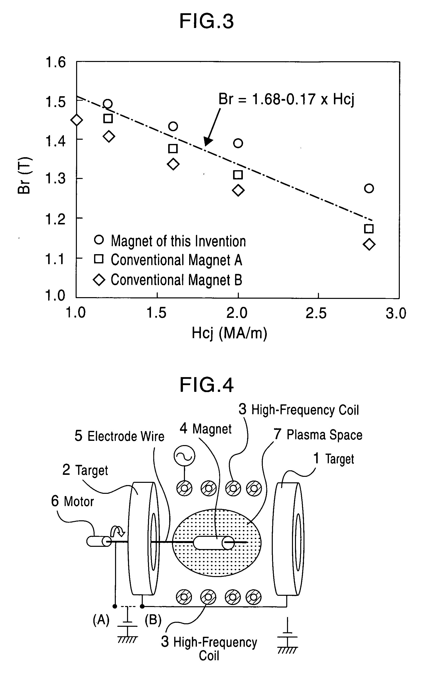
[0079] A sintered magnet block having a side length of 24 mm was prepared using an alloy having the same composition Nd12.5Fe78.5Co1B8, as in Example 1 as a starting raw material, and a disk-shaped magnet having an outer diameter of 4 mm, a thickness of 1 mm, and a volume of 12.6 mm3 was formed by cutting and grinding with a grindstone and discharge processing. In a three-dimensional sputtering apparatus, a target of each of Dy and Tb metals was mounted, and the magnet was inserted in a tungsten electrode wire coil. The two targets exchanged to deposit metal films on two respective magnets. In a film deposition work, as in Example 1, oxide films of the surface of each magnet were removed by reverse sputtering, and then a RF power of 60 W and a DC power of 200 W were applied to perform normal sputtering for 5 to 50 minutes, thereby forming a film of 2 to 18 μm.

[0080] Then, one of the two magnets was placed in an electric furnace in a glove box and heat-treated at 900° C. for 10 minu...

example 3

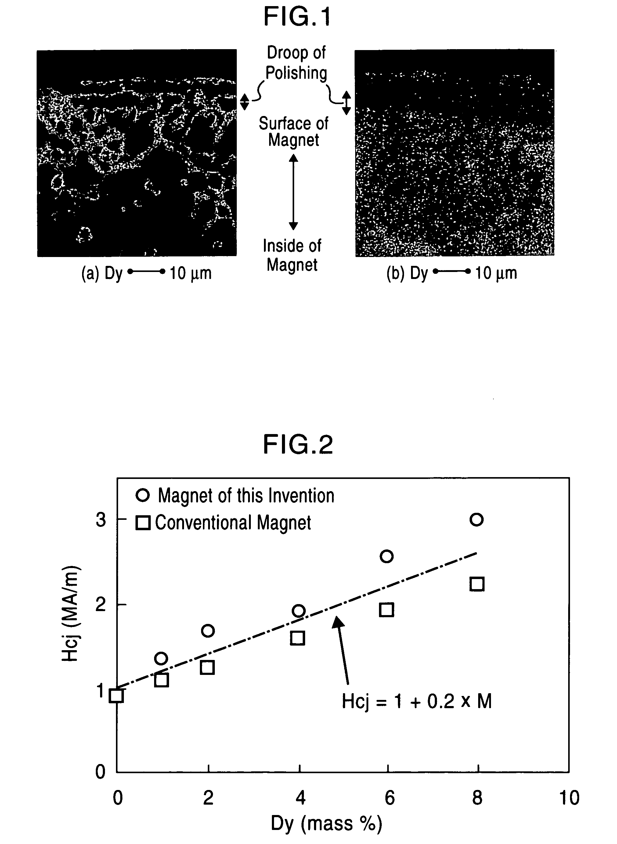
[0085] A disk-shaped magnet having an outer diameter of 4 mm, a thickness of 0.2 mm, 0.4 mm, 1 mm, 2 mm, or 4 mm was prepared from a raw material alloy having the composition Nd12Dy0.5Fe80B7.5 by the same process as in Example 2. Next, the magnet was mounted in a three-dimensional sputtering apparatus, and oxide films of the surface of the magnet were removed by reverse sputtering. Then, a RF power of 100 W and a DC power of 120 W were applied to perform normal sputtering for 15 minutes, thereby forming a Dy metal film of 2 μm on the surface of the magnet. Next, each magnet with the film deposited thereon was placed in an electric furnace in a glove box and heat-treated at 800° C. for 30 minutes to prepare samples (16) to (20) of the present invention. Also, a sintered magnet having an outer diameter of 4 mm and a thickness of 1 mm and not subjected to sputtering was prepared as a comparative example sample (8).

[0086] The magnetic properties of each sample were measured with a vibr...


PUM

PropertyMeasurementUnit
heat resistanceaaaaaaaaaa
crystal grain sizeaaaaaaaaaa
thicknessaaaaaaaaaa

Abstract

[Object] To provide a high-performance rare earth-based magnet exhibiting a high coercive force or a high residual magnetic flux density even when the content of a rare earth element such as Dy or the like which is scarce is reduced.
[Construction] A rare earth-iron-boron based magnet includes a crystal grain boundary layer enriched in element M (M is at least one rare earth element selected from Pr, Dy, Tb, and Ho) by diffusion of the element M from the surface of the magnet, wherein the relation between the coercive force Hcj and the content of the element M in the whole of the magnet is represented by the following expression: Hcj≧1+0.2×M (wherein 0.05≦M≦10) wherein Hcj is the coercive force (unit: MA/m), and M is the content of the element M in the whole of the magnet (% by mass). Furthermore, the magnet satisfies the following expression: Br≧1.68−0.17×Hcj wherein Br is the residual magnetic flux density (unit: T).

Description

TECHNICAL FIELD [0001] The present invention relates to a rare earth-iron-boron based magnet such as a Nd—Fe—B or Pr—Fe—B based magnet, and particularly to a high-performance magnet effectively utilizing a scarce metal, such as Dy or the like, and a method for production thereof. BACKGROUND ART [0002] Rare earth-iron-boron based magnets, particularly Nd—Fe—B based sintered magnets, are known as highest-performance magnets among permanent magnets and are widely used for voice coil motors (VCM) of hard disk drives, magnetic circuits of magnetic tomographic apparatuses (MRI), and the like. As magnets for these applications, magnets having a high residual flux density Br and a high maximum energy product (BH)max among magnetic properties are suitable, and coercive force Hcj may be low. [0003] On the other hand, heat resistance has been recently required for applications to electromobiles, and magnets having a high coercive force have been required for avoiding high-temperature demagneti...

Claims


Application Information

Patent Timeline
Patent Type & Authority Applications(United States)
IPC IPC(8): H01F1/057H01F1/053H01F1/08H01F41/02
CPCH01F41/0293H01F1/0575H01F1/032H01F1/057H01F1/053
Inventor MACHIDA, KENICHISUZUKI, SHUNJI
Owner JAPAN SCI & TECH CORP
Why Eureka
Try Eureka