Over-current protection device

Active Publication Date: 2007-02-15
POLYTRONICS TECH
View PDF6 Cites 17 Cited by
  • Summary
  • Abstract
  • Description
  • Claims
  • Application Information

AI Technical Summary

Benefits of technology

[0008] The objective of the present invention is to provide an over-current protection device. By adding a conductive powder (conductive filler) with a certain particle size distribution and at least one

Problems solved by technology

If the metal particles are used as the conductive filler, their larger particle size results in less uniform dispersion, and they are prone to be oxidized, which causes high resistance.
Since it lacks a rough surface like carbon black, the ceramic powder exhibits poor adhesion with the polyolefin polymer, and consequently, the resistance repeatability of the PTC conductive material is not well controlled.
However, the total resistance of the PTC conductive material after the coupl

Method used


Image

  • Over-current protection device
  • Over-current protection device
  • Over-current protection device

Examples


Example

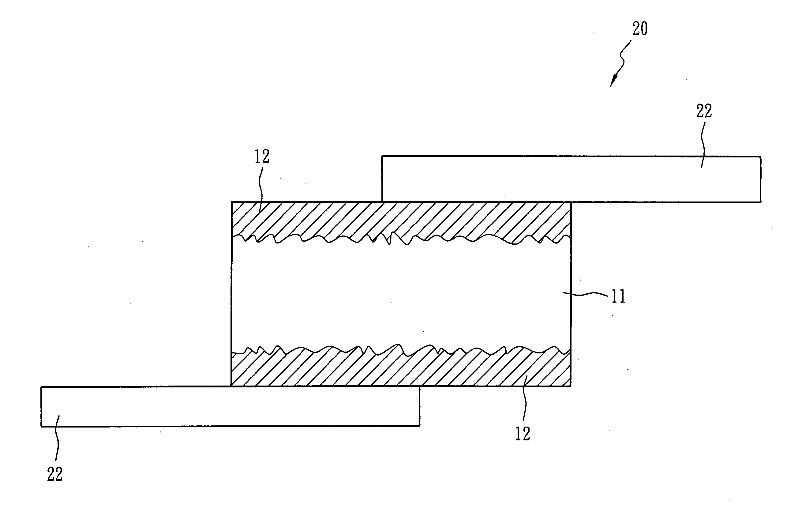
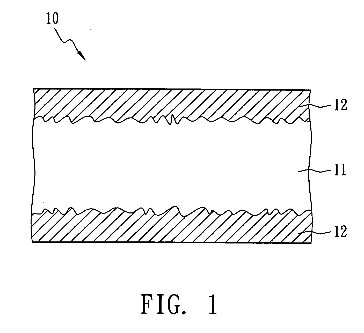
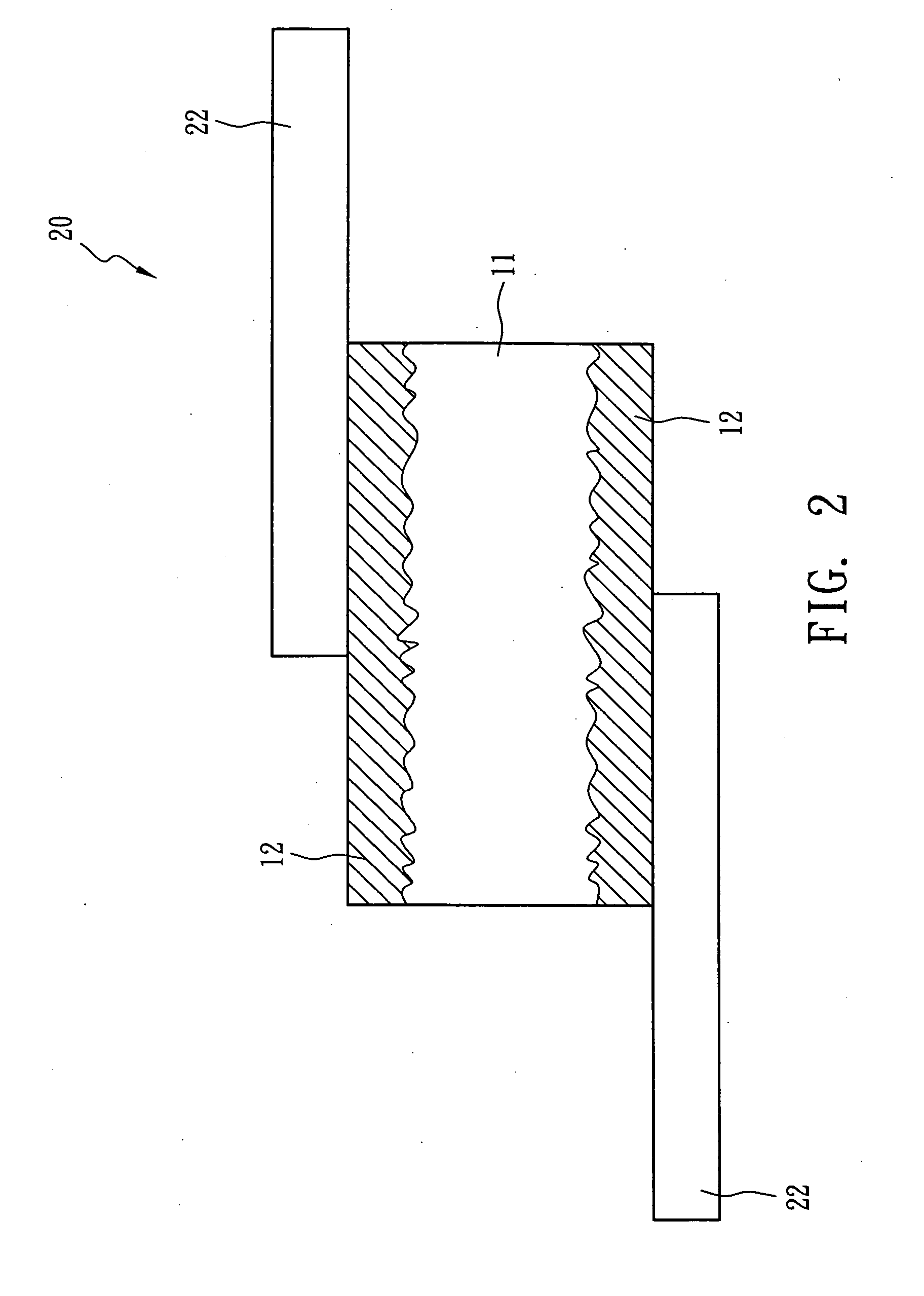
[0022] The following will describe the compositions and the manufacturing process of two embodiments (i.e., Example I and Example II) of the over-current protection device of the present invention with accompanying figures.

[0023] The composition and weight (unit in grams) thereof of the PTC material layer in the over-current protection device of the present invention and a comparative example are shown in Table 1 below. TABLE 1LDPE-1HDPE-1HDPE-2Mg(OH)2TiC(g)(g)(g)(g)(g)Example I12.660.50—6.0492.60Example II11.20——5.0493.60Comparative—3.1612.654.2090.90Example

[0024] In Table 1, LDPE-1 is a low-density crystalline polyethylene (density: 0.924 g / cm3; melting point: 113° C.); HDPE-1 is a high-density polyethylene (density: 0.943 g / cm3; melting point: 125° C.); HDPE-2 is a high-density polyethylene (density: 0.962 g / cm3; melting point: 131° C.); Mg(OH)2 is 96.9 wt % magnesium hydroxide mixed with 0.5% calcium oxide (CaO), 0.85% sulfamic acid (SO3), 0.13% silicon dioxide (SiO2), 0.03% i...


PUM


Abstract

An over-current protection device comprises two metal foils and a positive temperature coefficient (PTC) material layer. The PTC material layer is sandwiched between the two metal foils and comprises plural crystalline polymers with at least one polymer melting point below 115° C., and a non-oxide electrically conductive ceramic powder. The non-oxide electrically conductive ceramic powder exhibits a certain particle size distribution. The PTC material layer has a resistivity below 0.1 Ω-cm. The initial resistance of the device is below 20 mΩ, and the area of the PTC material layer is below 30 mm2. The over-current protection device exhibits a surface temperature below 100° C. under the trip state of over-current protection.

Description

BACKGROUND OF THE INVENTION [0001] 1. Field of the Invention [0002] The present invention relates to an over-current protection device and, more particularly, to an over-current protection device comprising a positive temperature coefficient (PTC) conductive material. The over-current protection device presents better resistivity and resistance repeatability, especially suitable to the protection of a power source used in portable communication applications. [0003] 2. Description of the Prior Art [0004] The resistance of PTC conductive material is sensitive to temperature change. With this property, the PTC conductive material can be used as current-sensing material and has been widely used in over-current protection devices and circuits. The resistance of the PTC conductive material remains at a low value at room temperature so that the over-current protection device or circuits can operate normally. However, if an over-current or an over-temperature situation occurs, the resistanc...

Claims


Application Information

Patent Timeline
IPC IPC(8): H01C7/13
CPCH01C7/027H01M50/572H01M2200/106
Inventor WANG, SHAU CHEWCHU, FU HUALO, KUO CHANG
Owner POLYTRONICS TECH
Why Eureka
Try Eureka