Enhanced data rate receiver

a data rate receiver and data rate technology, applied in the field of telecommunication systems, can solve the problems of increasing power consumption, mhz occupies chip area, increasing the complexity of demodulator blocks, etc., and achieves the effects of reducing power consumption, reducing power consumption, and reducing power consumption

Active Publication Date: 2007-02-15
TELEFON AB LM ERICSSON (PUBL)
View PDF11 Cites 13 Cited by
  • Summary
  • Abstract
  • Description
  • Claims
  • Application Information

AI Technical Summary

Benefits of technology

[0009] In one aspect the present invention provides a receive path in a receiver comprising:
[0010] a means for generating first digitized samples from a received analog signal at a first sampling rate,
[0011] an interpolating filter to generate second digitized samples which are estimates of samples obtainable by sampling the received analog signal at a second sample rate lower than the first sampling rate, second digitized samples being output at the first sampling rate and including at least one unusable sample, and
[0012] a circuit for generating a signal for controlling components of the receive path downstream of the interpolation filter to prevent processing of the unusable second digitized samples. The advantage of this arrangement is that a separate oscillator at the second sampling rate is not required while still allowing the second sampling rate to be a whole multiple of the baseband signal rate which is 1 MHz for Bluetooth.
[0013] The second digitized samples can be fed to an SRRC filter. The SRRC filter is configured to process samples at the second sample rate. The use of n SRRC filter in the receive path matched to an SRRC filter in the transmitter provides advantages in eliminating ISI.
[0014] The circuit for generating a signal can be a counter that transmits a signal at a certain count value of samples e.g. every time an unusable sample is to be processed by downstream components. A counter is a simple circuit which is cost-effective and takes up little chip area.

Problems solved by technology

The additional oscillator required to generate a whole multiple frequency of 1 MHz takes up chip area and increases power consumption.
The alternative—sampling at 13 MHz—increases the complexity of the demodulator block, increases power consumption and cost.

Method used


Image

  • Enhanced data rate receiver
  • Enhanced data rate receiver
  • Enhanced data rate receiver

Examples


Embodiment Construction

[0028] The present invention will be described with reference to certain drawings and to certain embodiments but this description is by way of example only.

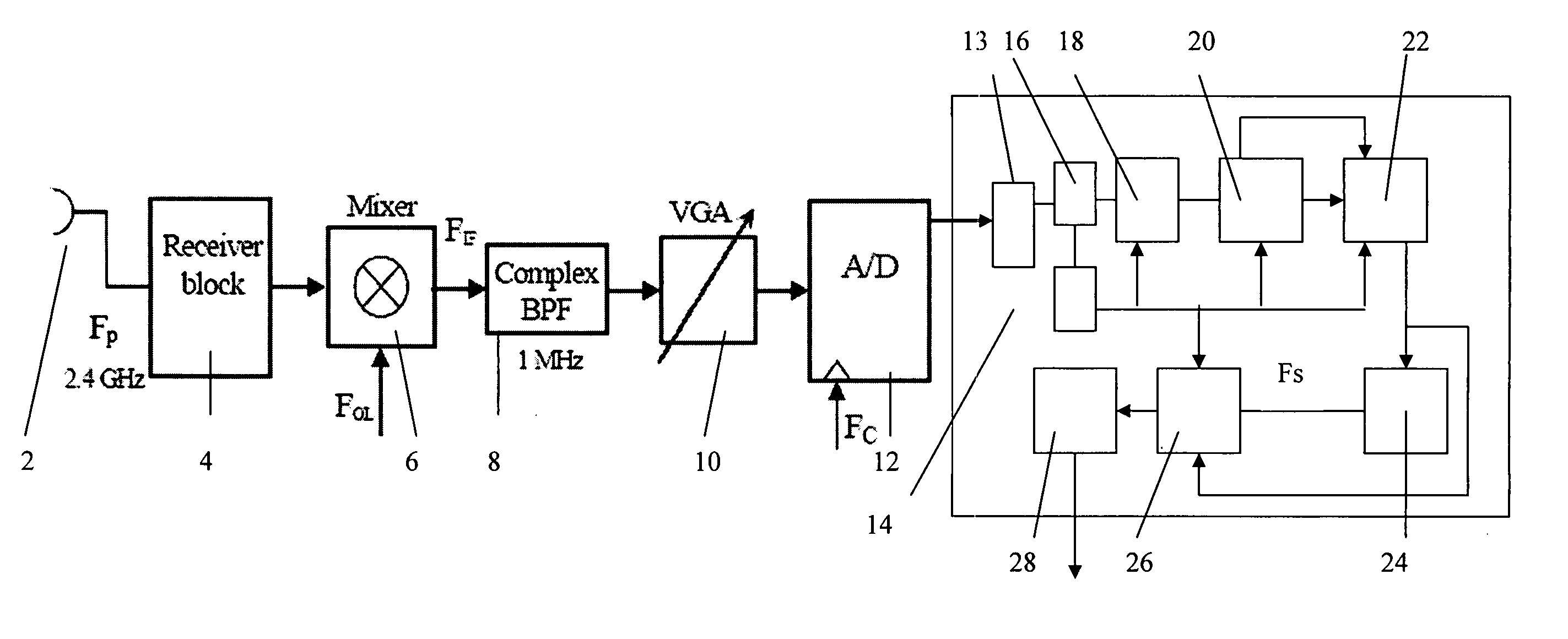
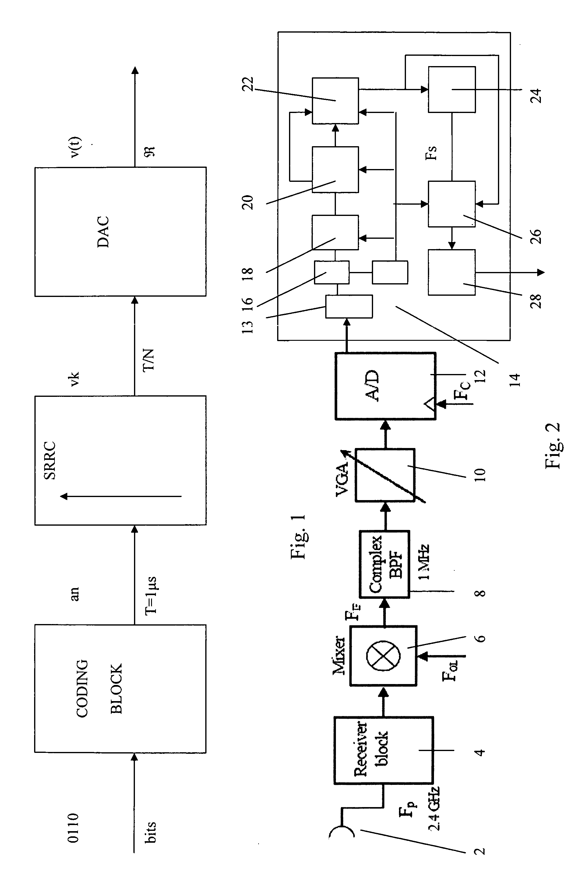
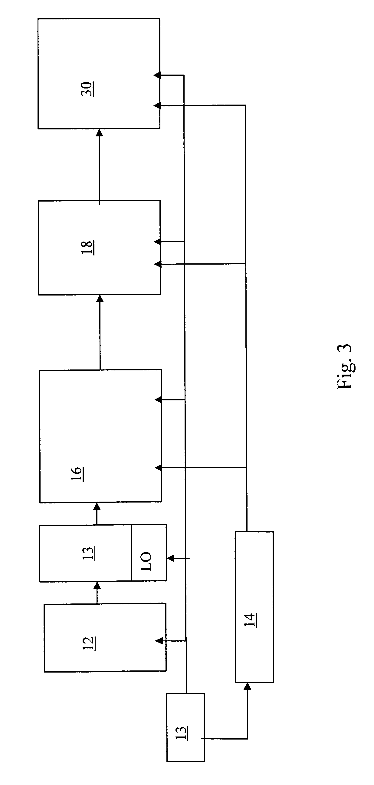
[0029]FIG. 2 shows a schematic representation of a receiver e.g. a receiver of a wireless transceiver such as a Bluetooth transceiver, in accordance with an embodiment of the present invention. FIG. 3 shows a detail thereof. The analog radio front end is an example only and is not limiting of the present invention. In the radio front-end the RF filters, oscillators, and image-reject mixers process input signals at high frequencies. To keep costs down, the input signal can be shifted to a lower intermediate frequency which allows on-chip construction of low power filters. The RF transmitted signal centered on 2.4 GHz is received at an antenna 2 and filtered by the Reception band-pass filter 4. An analog Down-Mixer 6 and a Complex band pass filter 8 are then used to obtain the bandpass signal, which occupies a 1 MHz-band centered ...


PUM


Abstract

A receiver having circuitry for generating first digitized samples from a received analog signal at a first sampling rate, e.g. an ADC. An interpolating filter is used to generate second digitized samples which are estimates of samples obtainable by sampling the received analog signal at a second sample rate lower than the first sampling rate, second digitized samples being output at the first sampling rate and including at least one unusable sample. A circuit is provided for generating a signal for controlling components of the receive path downstream of the interpolation filter to prevent processing of the unusable second digitized samples.

Description

BACKGROUND OF THE INVENTION [0001] 1. Field of the Invention [0002] The present invention relates to telecommunication systems especially wireless systems, wireless transmitters and wireless receivers, especially those using the Bluetooth standard. The present invention also relates to semiconductor integrated circuits that implement a wireless receiver and / or a wireless transmitter especially those using the Bluetooth standard, as well as software for implementing the transmitter and / or receiver. [0003] 2. Technical Background [0004] Version 2.0 +EDR of the Bluetooth standards introduces an Enhanced Data Rate (EDR) operation. The EDR standard is an improvement over the Basic Rate standard. New modulation schemes: π / 4-DQPSK and 8DPSK, are proposed. The bandwidth of the channel is 1 MHz. [0005] In the digital part of the receiver an SRRC filter is proposed which is matched with the SRRC filter used in transmitter. This filter behavior has been selected for Bluetooth EDR specification...

Claims


Application Information

Patent Timeline
Patent Type & Authority Applications(United States)
IPC IPC(8): H04H1/00H04H20/00
CPCH03H17/0685H03H17/0621
Inventor CAPRETTA, PIETRO
Owner TELEFON AB LM ERICSSON (PUBL)
Why Eureka
Try Eureka