Exhaust gas cleanup system

a technology of exhaust gas and cleaning system, which is applied in the direction of machines/engines, metal/metal-oxide/metal-hydroxide catalysts, chemical/physical processes, etc., can solve the problem of easy burning of trapped particulate materials, increase the strength against thermal shock or vibration, and reduce the heat stress applied to each honeycomb unit. , the effect of preventing the increase of pressure loss

Inactive Publication Date: 2007-02-22
IBIDEN CO LTD
View PDF24 Cites 55 Cited by
  • Summary
  • Abstract
  • Description
  • Claims
  • Application Information

AI Technical Summary

Benefits of technology

[0007] In this exhaust gas cleanup system, the first cleanup apparatus is disposed at a position of an exhaust path length of about 1 m or less from the internal combustion engine, so that the exhaust gas reaches the first cleanup apparatus while keeping a high temperature without great heat removal by the exhaust path (for example, exhaust pipe, or the like). As a result, the first catalyst supported by the first cleanup apparatus is quickly raised in temperature by the exhaust gas to sufficiently perform its catalyst function, so that trapped particulate materials are easily burned. On the downstream of the first cleanup apparatus, the second cleanup apparatus that converts the exhaust gas is disposed, so that harmful substances (NOx, HC, CO, and so on) produced due to combustion of the internal combustion engine and harmful substances (CO, etc.) produced due to imperfect combustion of a part of the particulate materials trapped in the first cleanup apparatus can be converted. Therefore, the first cleanup apparatus can be easily regenerated and a plurality of harmful substances can be converted. Herein, “exhaust path length from the internal combustion engine” means the length from the extreme upstream portion of exhaust gas flow to the front end of the first cleanup apparatus. Also, “predetermined supporting amount” may be defined as a supporting amount that sufficiently purifies / converts the harmful substances contained in the exhaust gas.
[0008] In the exhaust gas cleanup system of the invention, the first cleanup apparatus preferably has a porosity of about 60% or more, more preferably about 75% or more, and most preferably about 80% or more. The porosity of about 60% or more preferably allows efficient burning of particulate materials since the particulate materials trapped in the first cleanup apparatus easily come into contact with the first catalyst supported by the first cleanup apparatus. The first cleanup apparatus preferably has a porosity of about 95% or less. The porosity of about 95% or less preferably prevents the material forming the wall of the first cleanup apparatus from being reduced, thus keeping the strength of the first cleanup apparatus.
[0009] In the exhaust gas cleanup system of the invention, the first cleanup apparatus may be a honeycomb filter including lamination in the longitudinal direction of two or more sheet-like members with a plurality of through holes so as to communicate the through holes with each other to form communicating holes. Thereby, even when a temperature difference occurs in the longitudinal direction of the first cleanup apparatus due to combustion heat of the particulate materials and a heat stress is applied, the stress is reduced between the lamination of the sheet-like members, so that damage due to the heat stress is less likely to occur than in the case of integral molding in the longitudinal direction. In the honeycomb filter, the end faces of the plurality of through holes may be alternately clogged.
[0011] In the exhaust gas cleanup system of the invention, the second cleanup apparatus may be disposed at a position of an exhaust path length of about 3 m or less from the internal combustion engine. Thereby, the exhaust gas reaches the second cleanup apparatus without great heat removal by the exhaust path (for example, an exhaust pipe), so that the second catalyst supported by the second cleanup apparatus is made to function by using the exhaust gas heat, and a plurality of harmful substances contained in the exhaust gas are easily converted.
[0012] In the exhaust gas cleanup system of the invention, the second cleanup apparatus may be a honeycomb structure including a porous honeycomb unit that have a plurality of through holes and have a sectional area of about 50 cm2 or less orthogonal to the through holes, and a sealing material layer that joins two or more of the porous honeycomb units on their outer faces with no through holes being open. Thereby, the plurality of porous honeycomb units are structured so as to be joined to each other via a sealing material layer, so that strength against thermal shock or vibrations can be increased. When the area of the section orthogonal to the through holes is about 50 cm2 or less, the size of the honeycomb unit does not become excessively large and a heat stress applied to each honeycomb unit is sufficiently reduced. In addition, the sectional area of the plane orthogonal to the through holes is preferably about 5 cm2 or more. The sectional area of about 5 cm2 or more is preferable since the sectional area of the sealing material layer that joins a plurality of porous honeycomb units does not become relatively large and the specific surface area to support the catalyst does not become relatively small, thus preventing the pressure loss from being increased. Herein, the sectional area of the porous honeycomb unit means the sectional area of the porous honeycomb unit as a basic unit forming the honeycomb structure when the honeycomb structure includes a plurality of porous honeycomb units with different sectional areas, and is normally the maximum sectional area of the porous honeycomb unit. In addition, the total sectional area of the porous honeycomb units preferably occupies about 85% or more of the sectional area of the honeycomb structure, and more preferably, occupies about 90% or more. When the total sectional area of about 85% or more, the percentage of the total sectional area is the sealing material layer to the sectional area of the honeycomb structure does not become relatively high, the total sectional area of the porous honeycomb units is not excessively reduced, so that the specific surface area supporting the catalyst does not become relatively small and the pressure loss does not increase.

Problems solved by technology

As a result, the first catalyst supported by the first cleanup apparatus is quickly raised in temperature by the exhaust gas to sufficiently perform its catalyst function, so that trapped particulate materials are easily burned.

Method used


Image

  • Exhaust gas cleanup system
  • Exhaust gas cleanup system
  • Exhaust gas cleanup system

Examples


example 1

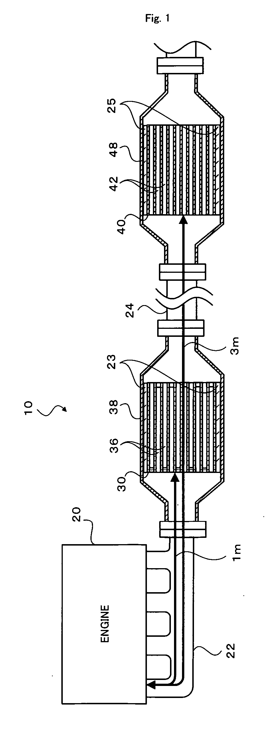
[0069] Hereinafter, an example (example 1) of an exhaust gas cleanup system 10 using the honeycomb filter 30 and the honeycomb structure 40 is described.

[0070] Method for Manufacturing a Honeycomb Filter 30 (DPF-A)

[0071] A honeycomb filter 30 that contains alumina fibers (average diameter: 5 μm, average length: 300 μm) as inorganic fibers was manufactured. Alumina fibers were dispersed in the proportion of 10 g to 1 L of water, silica sol was added in the proportion of 5 weight percent to alumina fibers, an acryl resin was added in the proportion of 3 weight percent, and furthermore, small amounts of aluminum sulfate and polyacrylamide were added and sufficiently stirred, whereby a papermaking slurry was prepared. This papermaking slurry was screened through a perforated mesh having square holes formed at predetermined intervals, and then the obtained article was dried at 150° C., whereby a sheet-like member 31 was obtained which had a diameter of 143.8 mm, a thickness of 1 mm, th...

example 2

[0078] Next, an example (example 2) of an exhaust gas cleanup system 10 using the honeycomb filter 130 and the honeycomb structure 140 is described.

[0079] Method for Manufacturing Honeycomb Filter 130 (DPF-B)

[0080] 7000 parts by weight of α-type silicon carbide powder (average particle diameter: 10 μm), 3000 parts by weight of α-type silicon carbide powder (average particle diameter: 0.5 μm), 1000 parts by weight of acryl particles as a pore forming agent, and 3700 parts by weight of water were mixed, and furthermore, 2000 parts by weight of methylcellulose as an organic binder, 300 parts by weight of glycerin as a plasticizer, and 660 parts by weight of a lubricant (product name: UNILUB made by NOF Corporation) were added and kneaded, whereby a green body was obtained. This green body was extruded into a rectangular column shape having a plurality of through holes arranged side by side in the longitudinal direction to obtain a raw molding. Next, the obtained raw molding was dried...

examples 3 , 6

Examples 3, 6, and 9

[0085] In the examples 3, 6, and 9, the same DPF-A and NSC-D as those of the example 1 were used. In the example 3, a DPF-A sample was disposed at a position of 1 m in length from the engine 20, and a NSC-D sample was disposed at a position of 1.2 m in length from the engine 20. In the example 6, a NSC-D was disposed at a position of 3 m in length from the engine 20, and a DPF-A was disposed at a position of 3.2 m in length from the engine 20. In the example 9, a DPF-A sample was disposed at a position of 3 m in length from the engine 20, and an NSC-D sample was disposed at a position of 3.2 m in length from the engine 20.


PUM

PropertyMeasurementUnit
path lengthaaaaaaaaaa
porosityaaaaaaaaaa
path lengthaaaaaaaaaa

Abstract

An exhaust gas cleanup system 10 includes a honeycomb filter 30 disposed at a position of an exhaust path length of about 1 m or less from the engine 20 (length from the extreme upstream portion of a manifold 22 to the front end of the honeycomb filter 30), and a honeycomb structure 40 disposed at a position of an exhaust path length of about 3 m or less from the engine 20.

Description

CROSS-REFERENCE TO RELATED APPLICATIONS [0001] The present invention is a continuation of International Application No PCT / JP2005 / 015551, filed on Aug. 26, 2005 and now abandoned, which claims priority from Japanese Patent Application No. 2004-252889 filed on Aug. 31, 2004. BACKGROUND ART [0002] 1. Field of the Invention [0003] The present invention relates to an exhaust gas cleanup system. [0004] 2. Description of the Prior Art [0005] Conventionally, as an exhaust gas cleanup system, one has been proposed which includes a support that supports an NOx storage agent (barium, etc.) and an oxidation catalyst (platinum, etc.) disposed on the upstream of exhaust gas flow and a diesel particulate filter (hereinafter, referred to as DPF) supporting an oxidation catalyst (platinum, etc.) disposed on the downstream. For example, the apparatus disclosed in JP-A 2002-153733 regenerates the DPF by burning, at low temperature, particulate materials trapped by the DPF disposed on the downstream b...

Claims


Application Information

Patent Timeline
Patent Type & Authority Applications(United States)
IPC IPC(8): B01D46/00
CPCB01D53/9422F01N13/009B01D2255/1021B01D2255/2042B01D2255/402B01J23/58B01J35/04C04B38/0006C04B2111/00793C04B2111/0081F01N3/0215F01N3/0222F01N3/035F01N3/0807F01N3/0842F01N2330/30F01N2330/48F01N2340/02F01N2370/02B01D53/944C04B35/195C04B35/803C04B38/0054C04B38/0074C04B35/565C04B35/806B01D53/94F01N3/02F01N3/08F01N3/24
Inventor OHNO, KAZUSHIGE
Owner IBIDEN CO LTD
Why Eureka
Try Eureka