Process for producing ultrafine particles

a technology of ultrafine particles and processing equipment, which is applied in the field of process for producing ultrafine particles, can solve the problems of inability to produce precision sinter molding materials, inability to produce fine particles whose surfaces are coated with thin films, and inability to reduce the stability of fine particles, etc., and achieves high surface activity, novel functionality, and high level of particle size and shape uniformity

Active Publication Date: 2007-04-19
NISSHIN SEIFUN GRP INC
View PDF3 Cites 115 Cited by
  • Summary
  • Abstract
  • Description
  • Claims
  • Application Information

AI Technical Summary

Benefits of technology

[0027] The present invention has remarkable effects. In other words, according to the present invention, vapor-phase thin film formation on the surfaces of ultrafine particles which are expected to have a high surface activity and a novel functionality can be efficiently performed, and a process for producing ultrafine particles each coated with a thin film, which can realize high level uniformity in particle size and shape, can be obtained.
[0028] More specifically, according to the present invention, by introducing materials for producing ultrafine particles into a thermal plasma flame under reduced pressure to form a vapor-phase mixture, introducing a reactive...

Problems solved by technology

As described before, the smaller the size of the fine particles becomes, the higher the surface activity becomes, which conversely decreases the stability of the fine particles.
Accordingly, there is a problem to date in that the ultrafine particles whose surfaces are coated with a thin film and which are useful to various functional mater...

Method used


Image

  • Process for producing ultrafine particles
  • Process for producing ultrafine particles
  • Process for producing ultrafine particles

Examples


example 1

[0112] First, an example in which ultrafine particles of silver were produced and agglomeration and coalescence of the particles to each other were prevented is presented.

[0113] As a material, a silver powder having an average particle size of 4.5 μm was used.

[0114] Further, argon was used as a carrier gas.

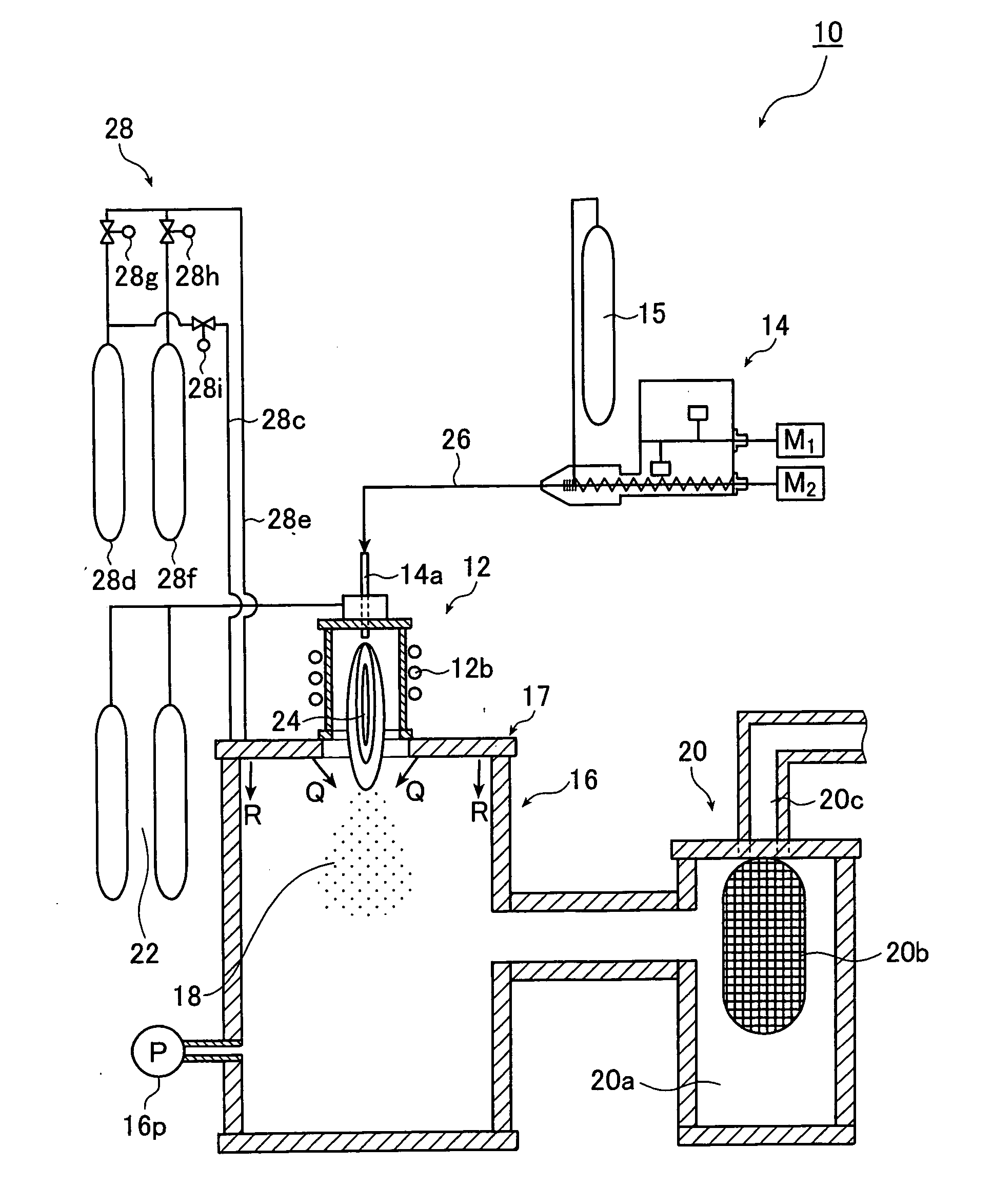
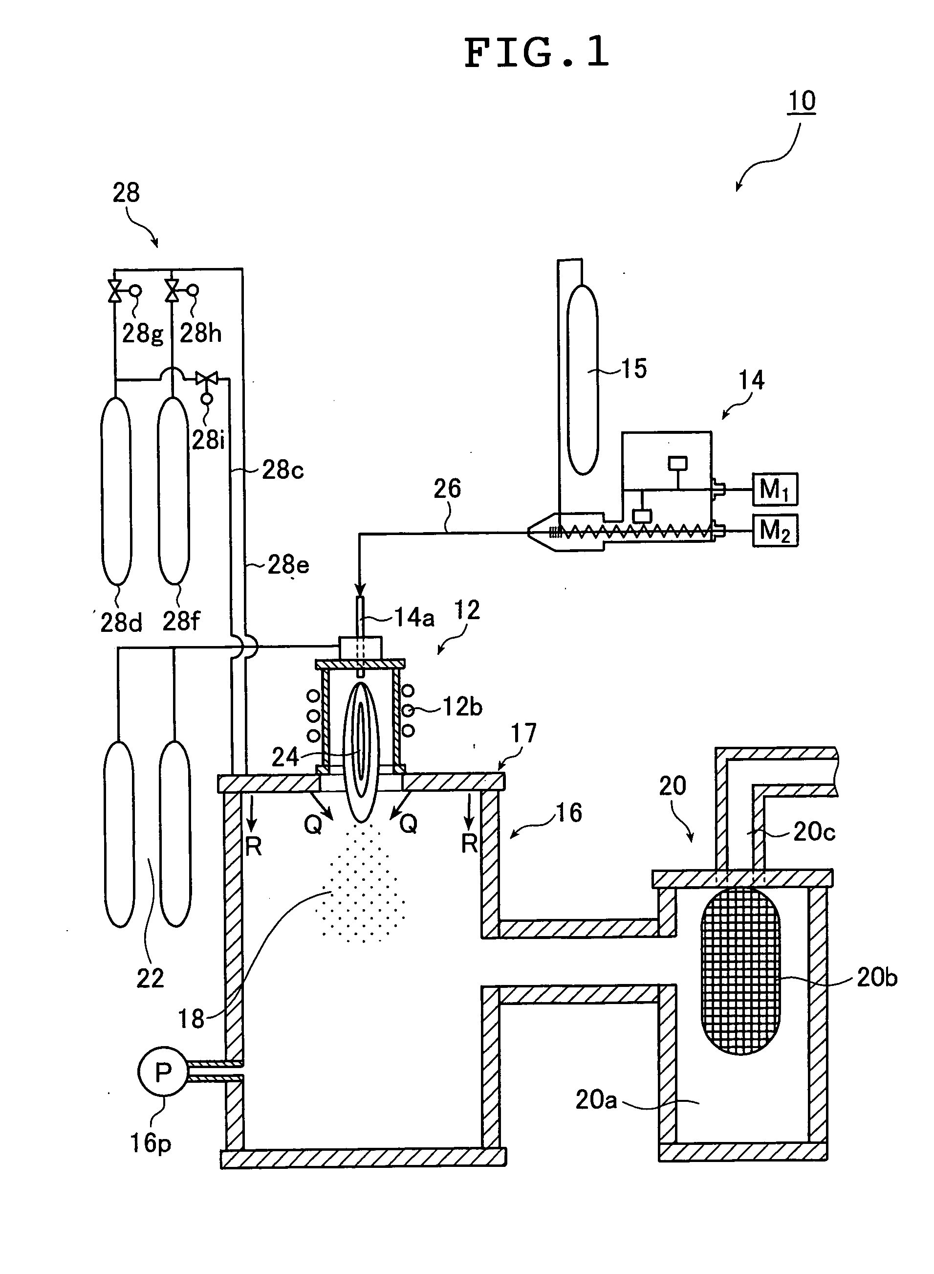
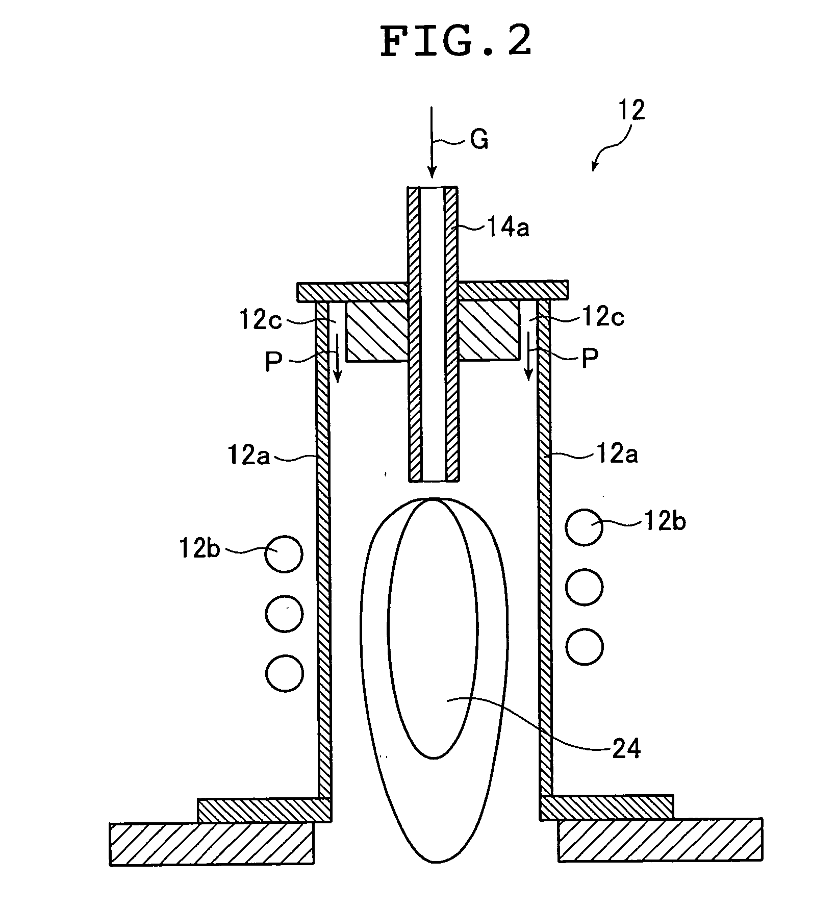
[0115] The high frequency oscillation coil 12b in the plasma torch 12 was applied with high frequency voltage of about 4 MHz and about 80 kVA, and a mixed gas of 80 liters / min of argon and 5 liters / min of hydrogen was introduced as the plasma gas from the plasma gas source 22 to generate an argon / hydrogen thermal plasma flame in the plasma torch 12. Note that, here, the reaction temperature was controlled to be about 8,000° C. and 10 liters / min of a carrier gas was supplied from the carrier gas source 15 of the material supplying apparatus 14.

[0116] The silver powder together with argon as a carrier gas was introduced into the thermal plasma flame 24 in the plasma torch 12.

[0...

example 2

[0121] Next, an example is shown in which the ultrafine silver particles were produced in the same manner as in Example 1, and the amount of the reactive gas was changed to control the particle size.

[0122] As the material, a silver powder having an average particle size of 4.5 μm was used.

[0123] Further, argon was used as the carrier gas.

[0124] Here, the high frequency voltage to be applied to the plasma torch 12 and the supply amount of the plasma gas were the same as those used in Example 1, and an argon / hydrogen thermal plasma flame was generated in the plasma torch 12. Note that the reaction temperature was controlled to be about 8,000° C., and the supply amount of the carrier gas from the carrier gas source 15 of the material supplying apparatus 14 was set to 10 liters / min.

[0125] The silver powder was introduced into the thermal plasma flame 24 in the plasma torch 12 together with argon as the carrier gas.

[0126] Among the gases to be introduced into the chamber 16 by the g...

example 3

[0128] Next, an example will be shown in which ultrafine copper particles were produced and agglomeration and coalescence between the particles were prevented.

[0129] As the material, a copper powder having an average particle size of 5.0 μm was used.

[0130] Further, argon was used as the carrier gas.

[0131] Here, the high frequency voltage to be applied to the plasma torch 12 and the supply amount of the plasma gas were the same as those used in Examples 1 and 2, and an argon / hydrogen thermal plasma flame was generated in the plasma torch 12. Note that the reaction temperature was controlled to be about 8,000° C., and the supply amount of the carrier gas from the carrier gas source 15 of the material supplying apparatus 14 was set to 10 liters / min.

[0132] The copper powder was introduced into the thermal plasma flame 24 in the plasma torch 12 together with argon as the carrier gas.

[0133] Among the gases to be introduced into the chamber 16 by the gas introduction apparatus 28, the...


PUM

PropertyMeasurementUnit
Angleaaaaaaaaaa
Angleaaaaaaaaaa
Angleaaaaaaaaaa

Abstract

The ultrafine particle producing process introduces materials for producing ultrafine particles into a thermal plasma flame under reduced pressure to form a vapor-phase mixture, introduces a reactive gas and a cooling gas toward an end portion of the thermal plasma flame in supply amounts sufficient for quenching the vapor-phase mixture to generate the ultrafine particles and allows the resultant ultrafine particles to come into contact with the reactive gas so as to produce the ultrafine particles whose surfaces are coated with a thin film including one or more components compound derived from decomposition and/or reaction of the reactive gas, for example, an elementary carbon substance and/or a carbon. According to the process, thin film-coated ultrafine particles having high level uniformity in particle size and shape can be produced.

Description

[0001] The entire contents of the documents cited in this specification are herein incorporated by reference. BACKGROUND OF THE INVENTION [0002] The present invention relates to a process for producing ultrafine particles each coated with a thin film, and more particularly, to a process for producing ultrafine particles, each having a thin film including an elementary carbon substance and / or a carbon compound formed thereon, using a thermal plasma method. [0003] Fine particles such as oxide fine particles, nitride fine particles, and carbide fine particles have been used in the production of sintered bodies, for example, electrical insulating materials for semiconductor substrates, printed wiring boards, and various electrically insulating parts, materials for high-hardness and high-precision machining tools such as dies and bearings, functional materials for grain boundary capacitors, humidity sensors and the like, or precision sinter molding materials, and in the production of the...

Claims


Application Information

Patent Timeline
IPC IPC(8): B22F9/14B22F1/16
CPCB22F9/14B22F2998/00B22F2202/13B22F1/0018B22F1/02B22F2201/30Y10S977/895B22F1/16B22F1/054
Inventor NAKAMURA, KEITAROHFUJII, TAKASHI
Owner NISSHIN SEIFUN GRP INC
Why Eureka
Try Eureka