

Electroluminescent material and electroluminescent element using the same
- Summary
- Abstract
- Description
- Claims
- Application Information
AI Technical Summary
Benefits of technology
Problems solved by technology
Method used
Image

Examples
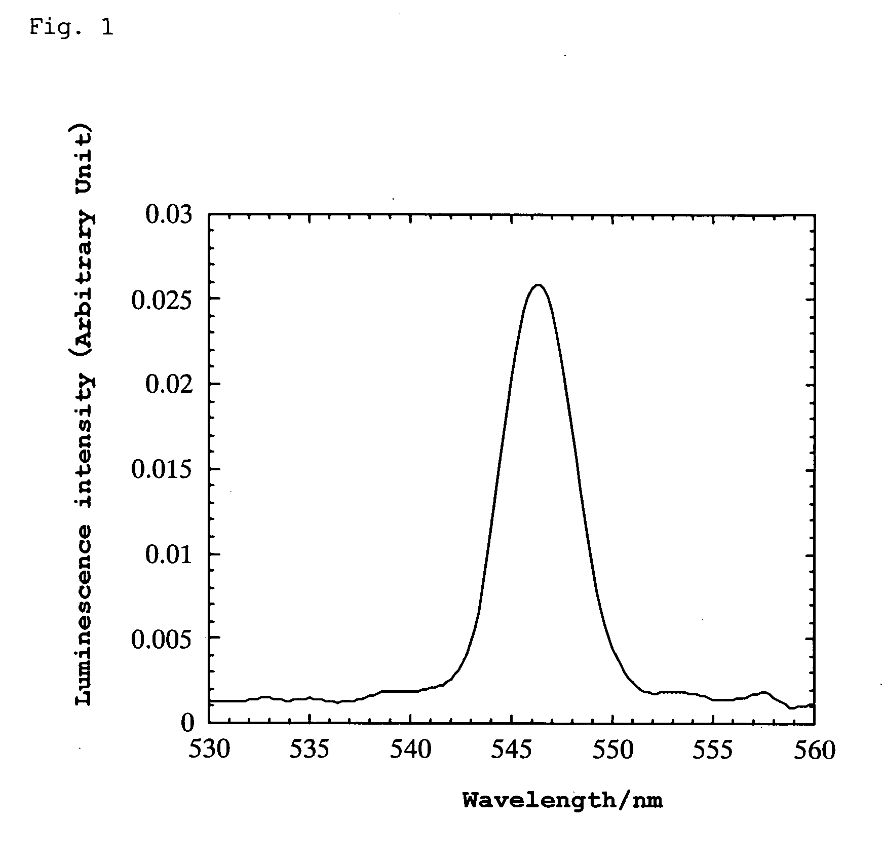
example 1
[0098] A thin plate having a diameter of about 2.0 mm and a thickness of about 0.245 mm was prepared by cutting and abrading a 0.1% (mole % of Ca relative to Al) calcium-doped YAlO3 single crystal (translucent white with very light purple) obtained by an FZ method.
[0099] An aluminum electrode layer (cathode) having a thickness of 150 nm was formed on one entire surface of the thin plate by a vacuum deposition method. A semicircular gold electrode layer (anode) having a thickness of 75 nm was formed on half of the other surface of the thin plate by a DC sputtering method.
[0100] A platinum wire was attached to the thin plate using silver paste and bipolar high AC voltage was applied thereto. When the AC voltage was varied at a frequency of 10 Hz, green luminescence was generated in the range of ±750 to 950 V. The wavelength at the luminescence peak was 546 nm. (However, even with varying the frequency over the range from 2 to 700 Hz, luminescence was not observed at ±500 V.) Lumines...
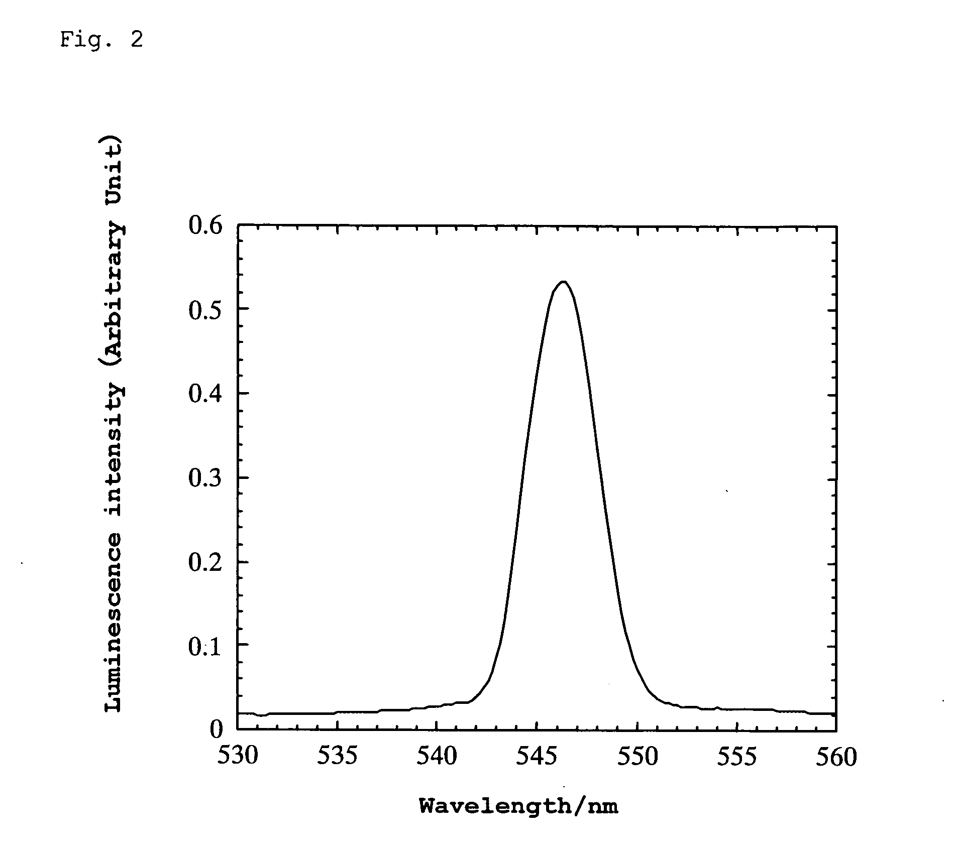
example 2
[0102] A thin plate having a diameter of about 2.1 mm and a thickness of about 0.137 mm was prepared by cutting and abrading 0.1% (mole % of Ti relative to Al) titanium-doped YAlO3 single crystal (translucent with light brown) obtained by an FZ method.
[0103] An aluminum electrode layer (cathode) having a thickness of 150 nm was formed on one entire surface of the thin plate by a vacuum deposition method. A semicircular gold electrode layer (anode) having a thickness of 75 nm was formed on half of the other surface of the thin plate by a DC sputtering method.
[0104] A platinum wire was attached to the thin plate using silver paste and bipolar high AC voltage was applied thereto. When the AC voltage was varied at a frequency of 10 Hz, green luminescence was generated in the range of ±550 to 900 V. The wavelength at the luminescence peak was 546 nm. (When the frequency was varied at ±500 V, luminescence was observed within the range of 250 to 600 Hz.) Luminescence was also observed un...
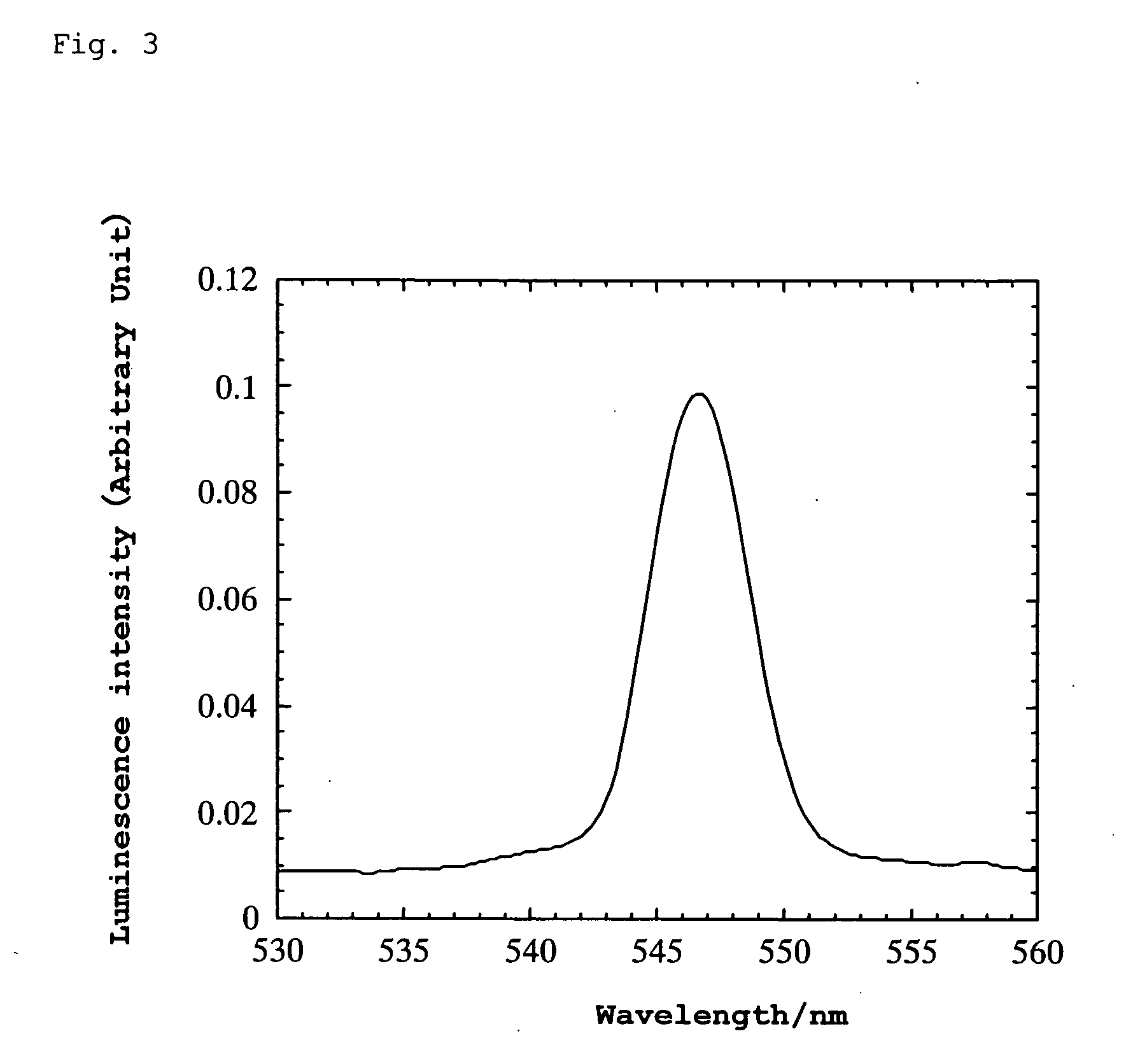
example 3
[0105] A thin plate having a diameter of about 2.1 mm and a thickness of about 0.137 mm was prepared by cutting and abrading 1% (mole % of Ti relative to Al) titanium-doped YAlO3 single crystal (translucent with light yellowish brown) obtained by an FZ method.
[0106] An aluminum electrode layer (cathode) having a thickness of 150 nm was formed on one entire surface of the thin plate by a vacuum deposition method. A semicircular gold electrode layer (anode) having a thickness of 75 nm was formed on half of the other surface of the thin plate by a DC sputtering method.
[0107] A platinum wire was attached to the thin plate using silver paste and bipolar high AC voltage was applied thereto. When the AC voltage was varied at a frequency of 10 Hz, green luminescence was generated in the range of ±275 to 375 V. The wavelength at the luminescence peak was 547 nm. (When the frequency was varied at ±500 V, luminescence was observed within the range of 2 to 60 Hz.) Luminescence was also observ...
PUM
| Property | Measurement | Unit |
|---|---|---|
| Fraction | aaaaa | aaaaa |
| Wavelength | aaaaa | aaaaa |
| Electroluminescence | aaaaa | aaaaa |
Abstract
Description
Claims
Application Information