

Methods for growing and harvesting carbon nanotubes
a carbon nanotube and carbon nanotube technology, applied in catalyst activation/preparation, metal/metal-oxide/metal-hydroxide catalysts, energy-based chemical/physical/physicochemical processes, etc., can solve the problem of not being able to obtain cnts and swnts in particular in quantities and forms necessary for practical applications, and achieve the effect of improving the quality of carbon nanotubes
- Summary
- Abstract
- Description
- Claims
- Application Information
AI Technical Summary
Problems solved by technology
Method used
Image

Examples
example 1
Growth and Harvest of SWNTs
[0048] (1) Catalytic Precursor Solution (to prepare the catalytic composition) [0049] Cobalt salt solution: dissolve 0.3100 g cobalt nitrate in a solvent such as isopropanol to make the total weight equal to 23.75 g., resulting in a Co concentration of 0.0442 mmol / g. [0050] Molybdenum salt solution: add 1 g Dl (deionized) water to 0.9058 g molybdenum chloride under a hood, shaking well to make sure all the molybdenum chloride is dissolved to form a brown solution. Dilute the solution with a solvent such as isopropanol to 25 g resulting in a Mo concentration of 0.1326 mmol / g.
[0051] Mix the Co and Mo solutions in equivalent weight and add 5% of a wetting agent such as tetraethylorthosilicate or other solvent described below. Other catalytic metals may be used as indicated above, including those in Group VIII, Group VIb, Group Vb, and Re. Solvents which may be used to dissolve the catalytic metal components include, but are not limited to, methanol, ethanol...
example 2
(A) Growth of SWNTs on Catalytic Flat Substrates Forming Two-Dimensional Arrays
[0072] Effects of Gas pressure on SWNT density on the catalytic flat substrate.
[0073] SWNTs were grown on the Co-Mo / Si wafer surface for 30 min at 750° C., under different CO pressures. The catalytic flat substrates (wafers) were prepared following the recipe described in Example 1.
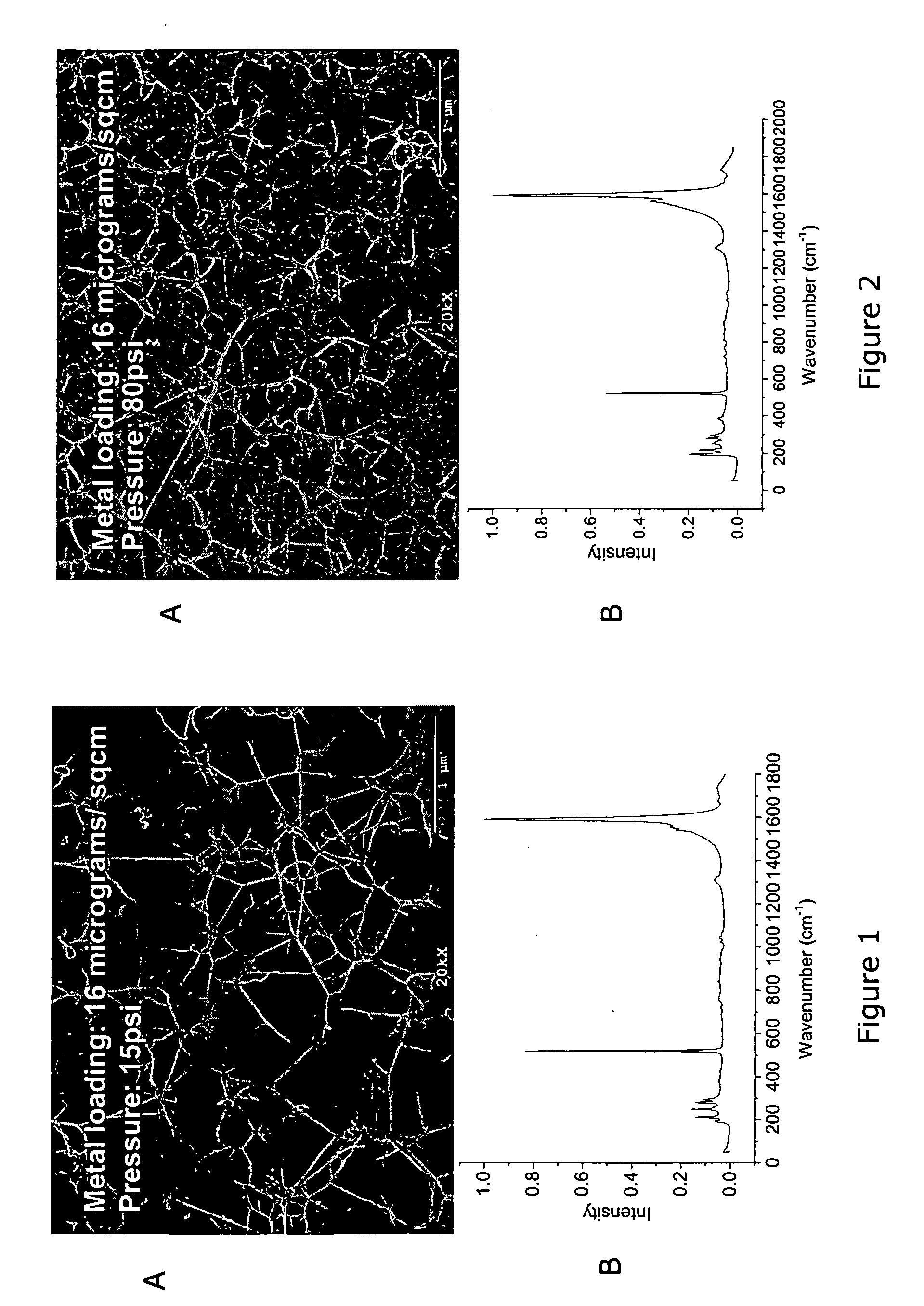
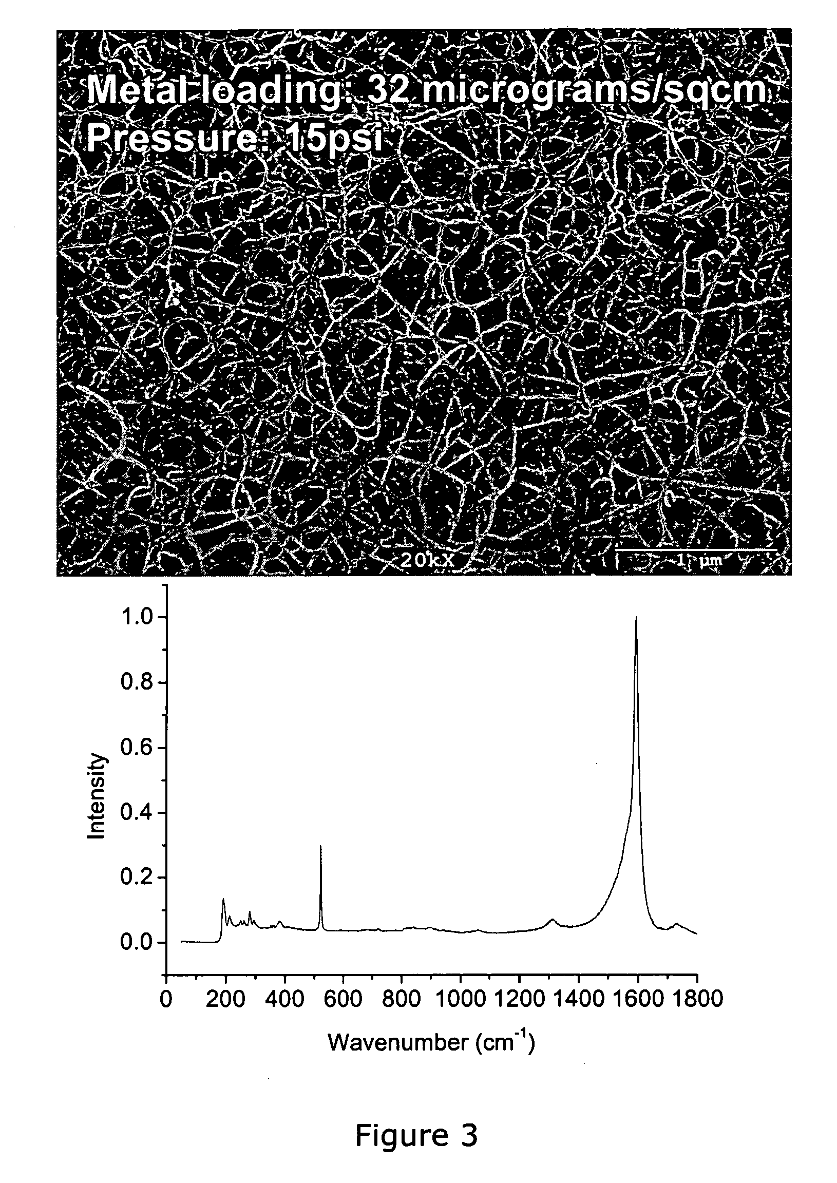
[0074] The resulting CNT structures, as observed by scanning electron microscopy (SEM) are illustrated in FIGS. 1 and 2. FIG. 1A shows growth of SWNTs at a lower pressure (15 psig) and shows a lower density of SWNTs than in FIG. 2A, which showed a higher SWNT density obtained at higher pressure (80 psig). The corresponding Raman spectra (FIGS. 1B and 2B) give clear evidence for the presence of SWNTs; that is, strong breathing mode bands (at 200-300cm−1), characteristic of SWNT), sharp G bands (1590 cm−1) characteristic of ordered carbon in sp2 configuration, and low D bands (1350 cm−1), characteristic of disordered carbon in...
example 3
(A) Transfer of SWNTs from the catalytic flat substrate onto a transfer medium
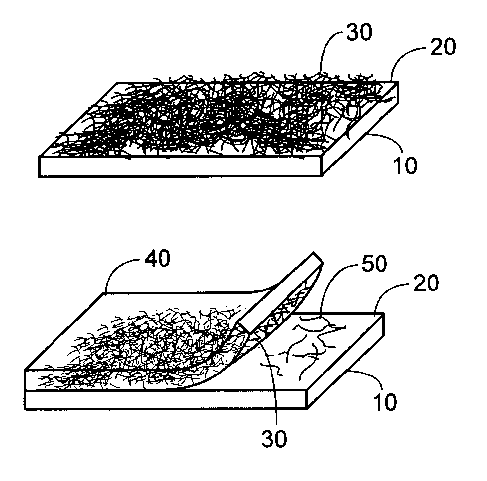
[0079] In one embodiment of the invention, after the SWNTs are formed on the catalytic flat substrate having the catalytic material thereon, they are transferred to a transfer medium comprising a polymeric film or other material (e.g., metal, ceramic, disordered film, elastomer, or carbon) deposited onto the catalytic flat substrate bearing the SWNTs (see Example 1, Step 5). The transfer medium may have an adhesive material thereon for enhancing adherence of the SWNTs thereto. A schematic representation of the transfer process is shown in FIG. 4. FIG. 4A shows a flat substrate 10 having a catalytic surface 20 thereon, and a SWNT mass 30 present on the catalytic surface 20. A transfer medium 40, (e.g., a polymeric material) is applied to the catalytic surface 20 of the flat substrate 10 and upon the SWNT mass 30 (FIG. 4B), wherein the transfer medium 40 is allowed to cure (if necessary), thereby causing tr...
PUM
| Property | Measurement | Unit |
|---|---|---|
| Temperature | aaaaa | aaaaa |
| Temperature | aaaaa | aaaaa |
| Fraction | aaaaa | aaaaa |
Abstract
Description
Claims
Application Information