Methods and systems for delivery of fluidic samples to sensor arrays

Active Publication Date: 2007-04-26
BL TECH INC
View PDF39 Cites 46 Cited by
  • Summary
  • Abstract
  • Description
  • Claims
  • Application Information

AI Technical Summary

Benefits of technology

[0015] In one aspect, the invention is directed to a sample-volume controlled sensor system for simultaneously measuring multiple analyte concentrations in chemical or biological substances such as water systems comprising a set of reversible and irreversible analyte-responsive sensor elements which are selected to change at least one optical property in response to chemical, biological, or environmental stimuli, including at least one reference region that serves as an internal optical and position standard, and a light source for directing light onto an array of sensor elements. A detector-based imaging device is provided which can adjust its performance to the position and spectral profile of the light source, and then converts this imaged response into a digital record. Image identification algorithms are provided to identify the test composition on the element by one of many configurations based on image intensity, color pattern, arrangement, and the like. A software-based optimization algorithm is provided which incorporates responses from the sensor array and produces optimized results unavailable without full system and variable compensation.
[0016] In another aspect, the invention is directed to a device comprising channels and reservoirs capable of delivering a controlled amount of a liquid sample to multiple reservoirs containing an array of sensor elements within a given time period. The driving force for liquid transport within

Problems solved by technology

These chemical and biological analyses can be performed individually using single tests with post-test optimization to enhance the quality or accuracy of the results, but this serial approach has inherent flaws because multidimensional interactions are difficult to fully compensate using a serial approach.
Additionally, this approach can be time consuming and can produce erroneous results.
Introducing operator or system errors when tests are performed on different platforms or at different times further complicates this system.
The best way to overcome this limitation is to perform all the desired measurements simultaneously on the same platform, but current state of the art does not provide a fully integrated platform for such measurements.
Current electrochemical array technology allows operators to perform an arrayed test at a single time, but this is limited to those materials that respond to an electrochemical stimulus.
This system, although productive for some systems is limited by many of the common limitations of electrochemical systems, e.g., systematic problems at low and high ionic strength that effect electrochemical potentials.
Additionally, some of these systems can suffer from serious cross-reactivities or interferences, e.g., the cross-reactivity of common oxyanions or small cations like sodium, lithium, and potassium.
These systems are often limited by mechanics required for fluid flow and maintenance, or from cumbersome equipment like

Method used


Image

  • Methods and systems for delivery of fluidic samples to sensor arrays
  • Methods and systems for delivery of fluidic samples to sensor arrays
  • Methods and systems for delivery of fluidic samples to sensor arrays

Examples


example 1

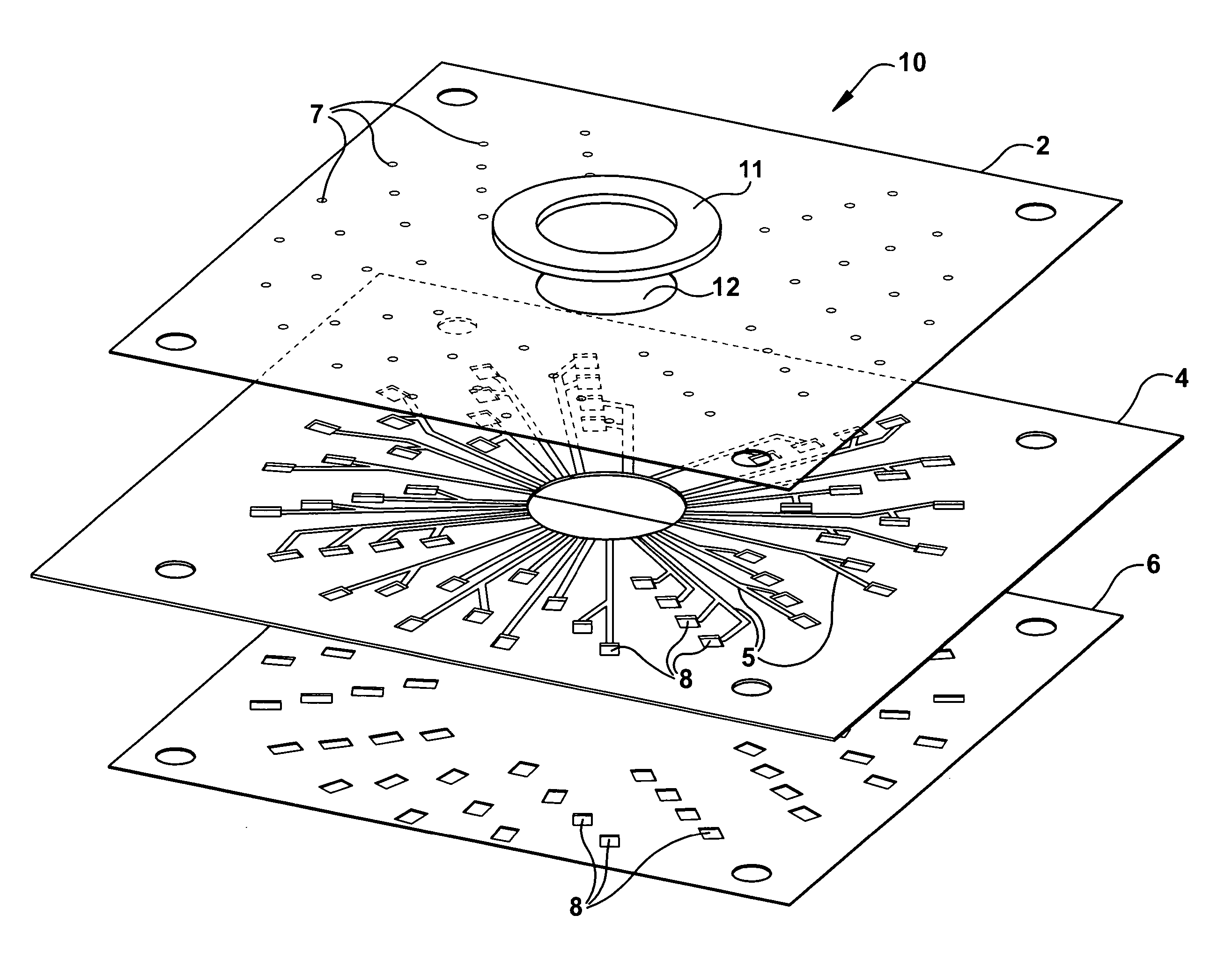
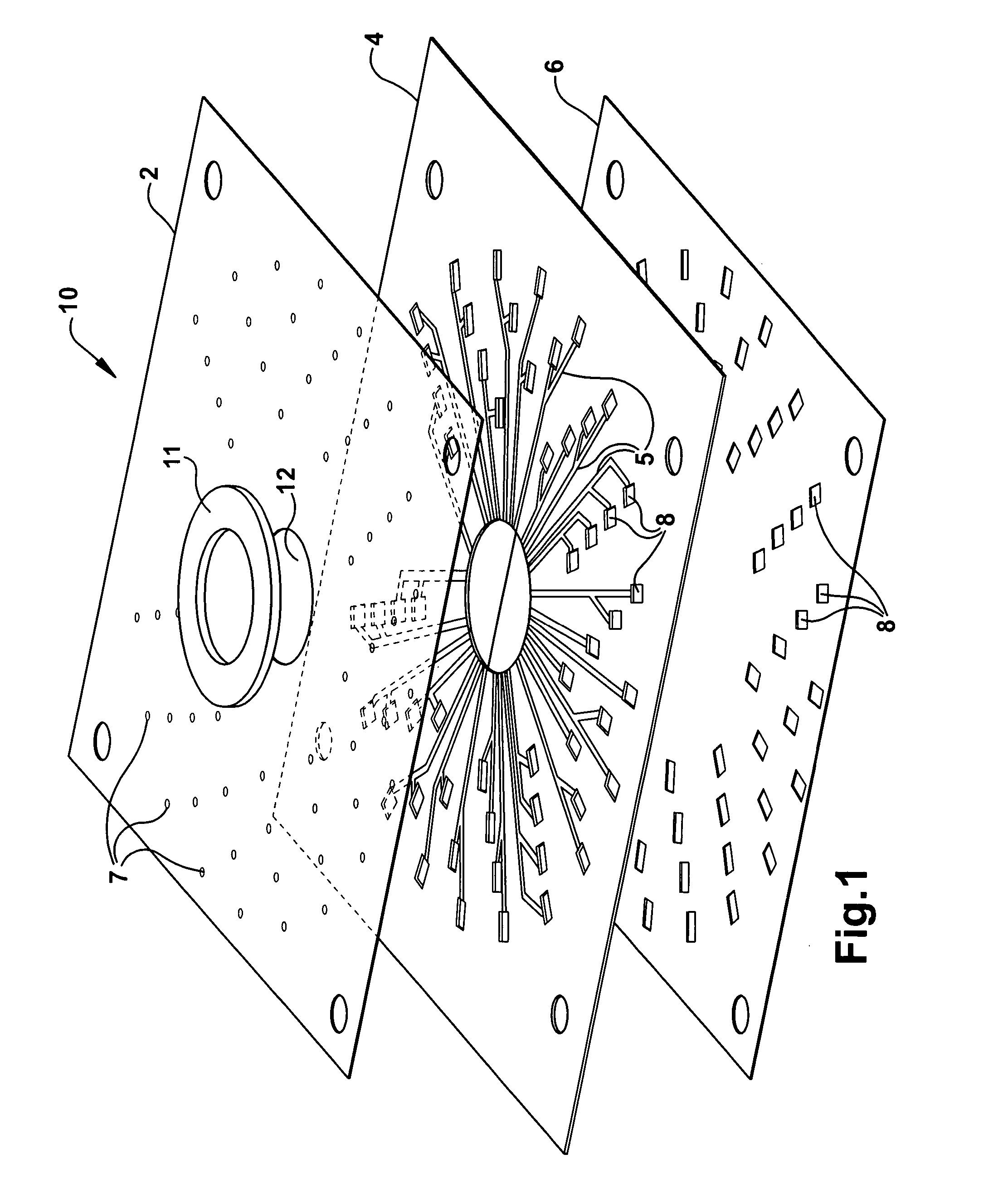
[0107] Reservoir fill time as a function of channel and reservoir geometric parameters. The channel and reservoir layout are shown in FIG. 20. The device comprises three layers as shown similarly in FIG. 1. The top cover layer 2 is a heat sealable hydrophilic film. Vent holes 7 (1.5 mm diameter) were cut through this layer. The middle channel layer 4 is a 0.78 mm thick polycarbonate sheet with open channels 5 and rectangle openings (i.e., reservoirs) 8 cut by means of computer numerical controlled (CNC) machining. The bottom sampler binding layer 6 is a 40 Shore A silicone gasket, providing seal to a substrate. Rectangle openings are die cut through the gasket. When these layers are laminated to form a fluid delivery device, channels are created between the top hydrophilic layer 2 and middle channel layer 4. The rectangle openings of the channel layer and sampler binding layer define an open-bottom reservoir, with the hydrophilic layer as its top wall. When this assembly is attached...

example 2

[0111] A 54-reservoir sample delivery device is shown in FIG. 1. The device 10 is assembled from four components by a method similar to that described in Example 1. The channel 5 depth and width are 0.33 mm and 1.5 mm, respectively. The length and width of reservoirs 8 are 5.5 and 4 mm, respectively. The sampler binding layer 6 is cut from a 0.55 mm thick, adhesive backed, and transparent silicone rubber sheet. The thickness of the polycarbonate channel layer 4 is 0.78 mm. Selection of these design parameters was guided by the equation shown in Example 1. A 2.7 ml sample solution containing 100 ppm Basic Blue was delivered to the sample entry port. Real time flow in the channels and reservoirs were monitored using a digital video camera. Fill time for each reservoir was retrieved from the recorded video films. Average fill times for all 54 reservoirs obtained from six devices are presented in FIG. 22. The data demonstrate that the device allows delivering a liquid sample to multiple...

example 3

Determination of Chlorine Concentration in a Water Sample

[0112] Six chlorine sensitive films were deposited on a thin translucent polyethylene sheet. A 20 μl chlorine standard solution, prepared from a 5% NaOCl by dilution with deionized water, was spotted on each film. The water sample was removed from the films 1 minute after spotting. A blue color was developed as chlorine in the water sample reacts with the chlorine sensitive reagent immobilized in the films. The image of these six films was captured with Hewlett Packard scanner ScanJet 6300C and is shown in FIG. 5. The digital file produced from the scanner was in the JPEG format (67 KB). The color depth was 255. The pixel resolution is 200 dpi.

[0113] The digital image was processed with Adobe Photoshop® 6. The film areas were selected using the selection tools provided by the Photoshop software package. Average RGB values for each selected color area are listed in Table 2 below. RGB values for the white paper area of the ima...


PUM

PropertyMeasurementUnit
Temperatureaaaaaaaaaa
Massaaaaaaaaaa

Abstract

Total analysis systems and methods for simultaneously monitoring a suite of biological and/or chemical species in water and/or other process systems are disclosed. The system provides a sample-volume controlled sensor array comprising a fluid delivery device and a plurality of optical sensor elements for determining the presence and total concentrations of multiple analytes in the process system simultaneously. Delivery means are provided to deliver a metered quantity of sample fluid to the sensor array. Image identification algorithms are provided for identifying the analytes based on image intensity, color pattern, positional arrangement, and the like. The methods incorporate multivariate optimization algorithms to analyze multiple sensor responses. This produces analytical results that are typically difficult to obtain without full system or variable compensation. The improved array response may then be utilized to measure, monitor, and control the concentration of analytes in the chemical or biological sample or water system.

Description

CROSS REFERENCE TO RELATED APPLICATION [0001] This application is a continuation-in-part of U.S. patent application Ser. No. 11 / 259,643 filed Oct. 26, 2005.FIELD OF INVENTION [0002] The present invention relates generally to a chemical sensor array, and more particularly relates to a new and improved system, method and apparatus for delivering a fluid sample to a chemical sensor array, and parallel processing chemical and biochemical information from a multiplicity of sensor elements of the sensor array. BACKGROUND OF THE INVENTION [0003] Many chemical and biological measurements need to be performed in locations outside of a fully equipped analytical facility. This requires systems that are portable and miniaturized so that they can be transported to locations where rapid test response is required for process or water quality monitoring, or they can be deployed in a medical environment to provide rapid test results for certain biological or biochemical species of interest. These ch...

Claims


Application Information

Patent Timeline
IPC IPC(8): G01N21/77
CPCB01L3/502715Y10T436/2575B01L3/50273B01L3/502746B01L2200/0605B01L2200/0642B01L2300/0806B01L2300/0816B01L2300/0864B01L2300/087B01L2400/0406B01L2400/0427B01L2400/0448G01N21/78G01N21/80G01N35/00069G01N2021/7766G01N2021/7773G01N2021/7783G01N2021/7786G01N2021/7793Y10T436/144444Y10T436/25B01L3/502723
Inventor POTYRAILO, RADISLAV A.SHRIKHANDE, PRASHANT V.BOYETTE, SCOTT M.XIAO, CAIBINLEACH, ANDREW M.
Owner BL TECH INC
Why Eureka
Try Eureka