
Ordered nanoenergetic composites and synthesis method

a nanoenergetic composite and nanoenergetic technology, applied in the field of nanotechnology, can solve the problems increasing the interfacial surface area between the fuel and the oxidizer, increasing the energy expended, and reducing particle size, so as to increase increase the amount of available surface area. , the effect of increasing the potential for high interfacial surface area

Inactive Publication Date: 2007-05-03
UNIVERSITY OF MISSOURI
View PDF25 Cites 57 Cited by
  • Summary
  • Abstract
  • Description
  • Claims
  • Application Information

AI Technical Summary

Benefits of technology

[0011] Production of fuel and oxidizer particles in the nanopartical size range increases the potential for high interfacial surface area. Smaller particle size increases the amount of available surface area. As greater surface area is generated, more it is likely to interface with the surface of different particles, even in random mixtures of particles. Thus, reduction of particle size has the potential to increase the interfacial surface area between the fuel and the oxidizer. Creating a nanorod in place of a nanosphere for at least one particle type also leads to an increase in surface area of about 40%.
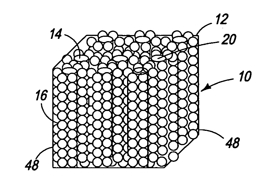
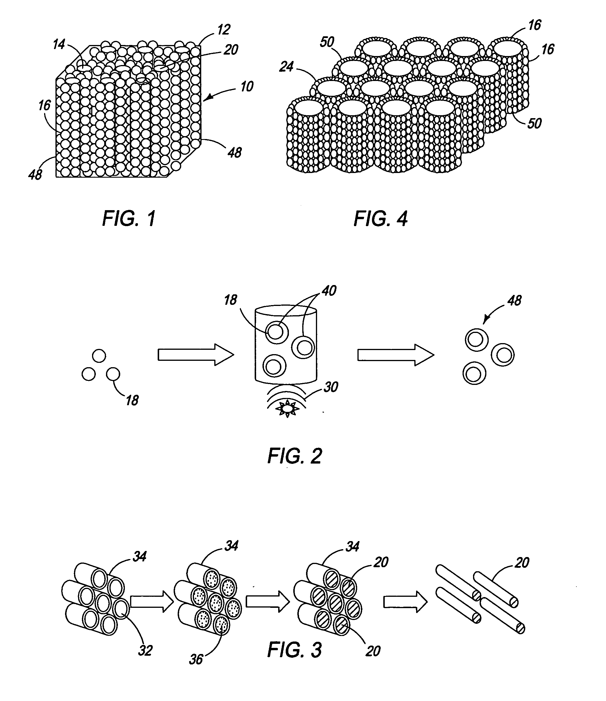
[0012] Structuring of the particles further adds to increases in the interfacial surface area. Placement of nanospheres of one material around nanorods of the other material assures at least some interfacial contact with the other material for each particle. This structure results in additional increases in interfacial surface area, leading to faster burn rates and increases in energy expended.

Problems solved by technology

Production of fuel and oxidizer particles in the nanopartical size range increases the potential for high interfacial surface area.
Thus, reduction of particle size has the potential to increase the interfacial surface area between the fuel and the oxidizer.
This structure results in additional increases in interfacial surface area, leading to faster burn rates and increases in energy expended.

Method used


Image

  • Ordered nanoenergetic composites and synthesis method
  • Ordered nanoenergetic composites and synthesis method
  • Ordered nanoenergetic composites and synthesis method

Examples


example 1

Synthesis of Copper Oxide Nanorods

[0046] For the synthesis of 5.045 g of copper chloride dihydrate (CuCl2.2 H2O, 99.5% Sigma Aldrich) was pulverized to a fine powder by grinding it in a mortar with a pestle. The finely powdered CuCl2.2H2O and 3.0 g NaOH were mixed together and 6.0 ml of PEG 400 (Polyethylene glycol 400, Alfa Aesar) was added into the mixture. This mixture was vigorously pulverized in a mortar for 45 minutes. During grinding, the copper chloride and sodium hydroxide were forced into the micelles of the PEG 400. The CuCl2 and NaOH then reacted to form CuO nanorods inside the micelles. The PEG 400 coating was removed by washing with water and ethanol.

example 2

Synthesis of Coated Aluminum Nanospheres

[0047] Aluminum nanoparticles were made by sonicating 0.42 g of aluminum in 300 ml of 2-propanol for 5 hours to achieve homogenous dispersion. To this solution, 1 ml of 0.1% solution of poly (4-vinylpyridine) in 2-propanol was added and the resultant solution was sonicated for an additional 2 hours. This solution was centrifuged until a clear supernatant was obtained. The solid recovered from the centrifuge was added to fresh 2-propanol, and the process of sonication followed by centrifugation was repeated 4-5 times to remove excess polymer. The coating that remained on the nanoparticles was substantially a monolayer.

example 3

Self-Assembly of Nanoenergetics

[0048] One gram of copper oxide nanorods was sonicated in 200 ml of 2-propanol for 4 hours. The well-dispersed aluminum nanoparticles were then added into the nanorod dispersion. Adter sonicating for 3 hours, the final solution was dried at 120° C. to obtain the self-assembled nanocomposite.


PUM

PropertyMeasurementUnit
frequencyaaaaaaaaaa
diameteraaaaaaaaaa
diameteraaaaaaaaaa

Abstract

A structured, self-assembled nanoenergetic material is disclosed that includes a nanostructure comprising at least one of the group consisting of a fuel and an oxidizer and a plurality of substantially spherical nanoparticles comprising at least the other of the group consisting of a fuel and an oxidizer. The spherical particles are arranged around the exterior surface area of said nanorod. This structured particle assures that the oxidizer and the fuel have a high interfacial surface area between them. Preferably, the nanostructure is at least one of a nanorod, nanowire and a nanowell, and the second shaped nanoparticle is a nanosphere.

Description

CROSS REFERENCE TO RELATED APPLICATION [0001] This application is related to U.S. Ser. No. ______ (Attorney Docket No. 2114.73713), entitled, “On-Chip Igniter and Method of Manufacture,” filed concurrently herewith and herein incorporated by reference.FIELD OF THE INVENTION [0002] This invention relates the use of nanotechnology to make metastable intermolecular composites (“MICs”) with tunable combustion characteristics. More specifically, nanoparticles of fuel and oxidizer are shaped and self-assembled to create ordered nanoenergetic composites to achieve higher burn rates resulting in creation of shock waves. BACKGROUND OF THE INVENTION [0003] Energetic materials are those that rapidly convert chemical enthalpy to thermal enthalpy. These materials are commonly known as explosives, propulsion fuels and pyrotechnics. Thermite is a well-known subgroup of pyrotechnics. It is a combination of a fuel and an oxidizer that combusts in a self-propagating reaction producing temperatures of...

Claims


Application Information

Patent Timeline
Patent Type & Authority Applications(United States)
IPC IPC(8): C06B33/00
CPCC06B33/00C06B45/00C06B45/02
Inventor GANGOPADHYAY, SHUBHRASHENDE, RAJESHSUBRAMANIAN, SENTHILGANGOPADHYAY, KESHABHASAN, SHAMEEM
Owner UNIVERSITY OF MISSOURI
Learn More