Polymer-ceramic dielectric composition, embedded capacitor using the dielectric composition and printed circuit board having the capacitor embedded therein

a technology of polymer-ceramic dielectric composition and embedded capacitor, which is applied in the direction of fixed capacitors, fixed capacitor details, conductive pattern formation, etc., can solve the problems of limited processing characteristics of printed circuit boards, large obstacles to miniaturization of final products, and various kinds of passive elements mounted on printed circuit boards

Active Publication Date: 2007-05-03
SAMSUNG ELECTRO MECHANICS CO LTD
View PDF12 Cites 16 Cited by
  • Summary
  • Abstract
  • Description
  • Claims
  • Application Information

AI Technical Summary

Benefits of technology

[0017] It is one object of the present invention to provide a polymer-ceramic dielect

Problems solved by technology

Various kinds of passive elements mounted on printed circuit boards are becoming great obstacles in the miniaturization of final products.
However, as the proportion of the cer

Method used


Image

  • Polymer-ceramic dielectric composition, embedded capacitor using the dielectric composition and printed circuit board having the capacitor embedded therein
  • Polymer-ceramic dielectric composition, embedded capacitor using the dielectric composition and printed circuit board having the capacitor embedded therein

Examples


example 1

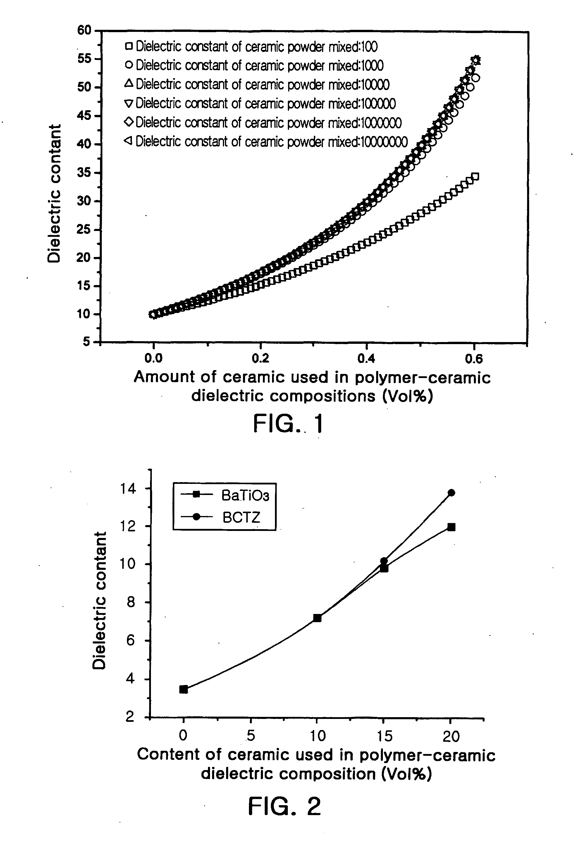
[0073] Ceramic powders were prepared in accordance with the compositions (Inventive Ceramics 1 to 6) indicated in Table 3. Each of the ceramic powders was ball-milled and mixed for 12 hours using ethanol as a solvent and zirconia balls. The mixture was dried at 200° C. for 12 hours, calcined and / or baked. The calcination was performed by heating the mixture at a rate of 5 ° C. / min., maintaining at the final temperature for 2 hours, and cooled. The thermally treated mixture was pulverized using ethanol as a solvent and zirconia balls for 24 hours, and dried at 200° C.

[0074] The dried ceramic powder was mixed with 20 vol % of a bisphenol A resin (epoxy type). Specifically, the mixing was carried out by mixing a bisphenol A resin, dicyanoguanidine as a curing agent and Re 610 as a dispersant together in acetone, and blending the mixture blended with the ceramic powder to prepare a slurry. At this time, the ratio of the bisphenol A resin and the curing agent was adjusted to 62:8.5 (w / w...

example 2

[0078] The procedure of Example 1 was repeated, except that CaO was further added to the ceramics, the calcined materials were pulverized so as to have an average particle diameter of about 1 μm, and the resulting powders were blended with 44 vol % of the resin.

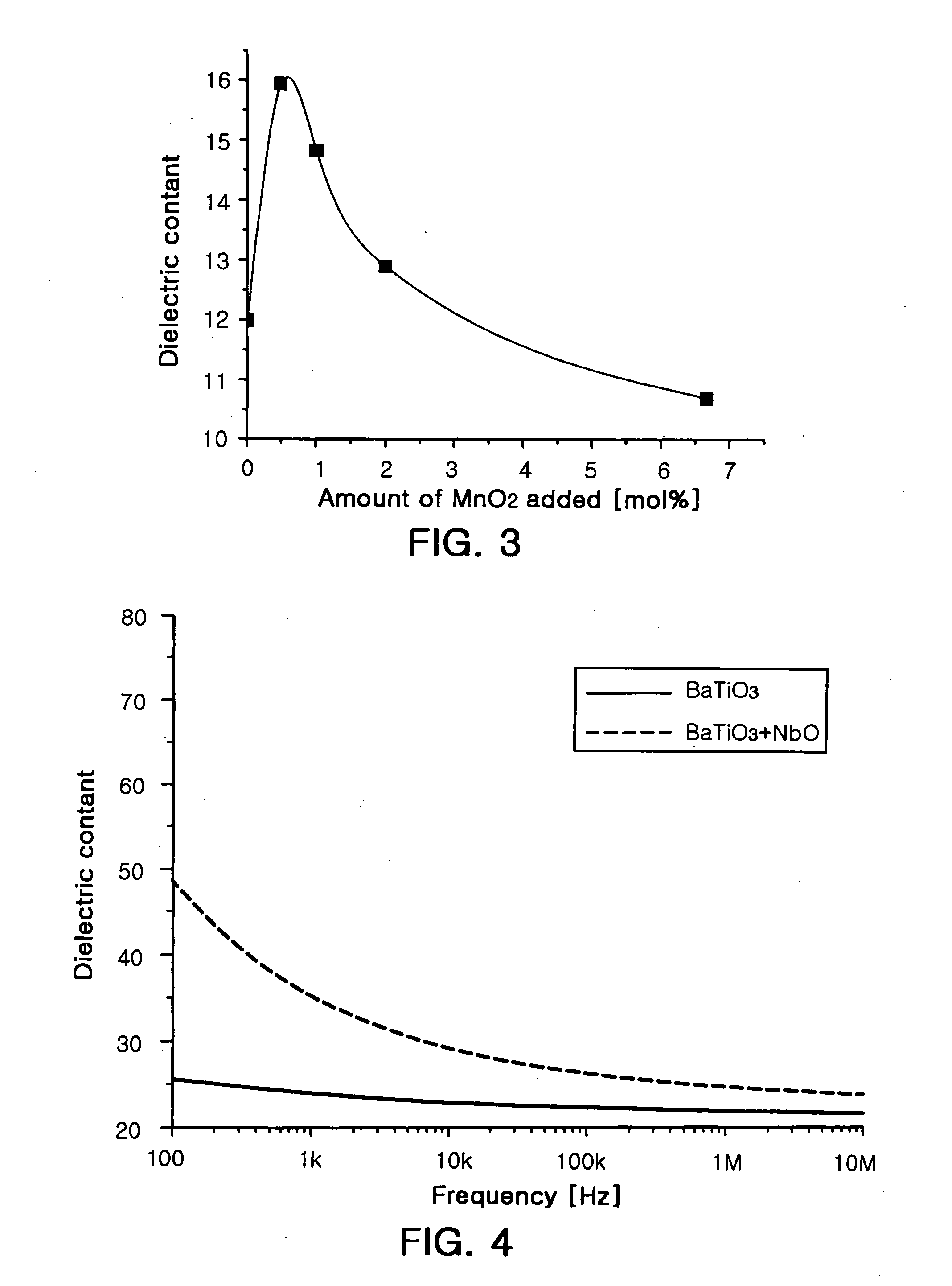
TABLE 4AmountAmountAmountCal-Dielec-LossofofOfciningtriccoeffi-NbOCaOBaTiO3temp.con-cientCeramic No.(mol %)(mol %)(mol %)(° C.)stant(Df)Conventional001001100220.05Ceramic 1Inventive22100110019.90.03Ceramic 7Inventive32100110043.70.09Ceramic 8Inventive42100110026.20.02Ceramic 9Inventive82100110026.10.02Ceramic 10

[0079] The results of Table 4 reveal that the addition of the Nb oxide and the Ca oxide caused a great increase in the dielectric constant of the dielectric compositions.

[0080] Although the present invention has been described herein with reference to the foregoing embodiments, these embodiments do not serve to limit the scope of the present invention. All modifications having substantially the same constitution and...


PUM

PropertyMeasurementUnit
Temperatureaaaaaaaaaa
Frequencyaaaaaaaaaa

Abstract

Disclosed herein is a polymer-ceramic dielectric composition. The dielectric composition comprises a polymer and a ceramic dispersed in the polymer wherein the ceramic is composed of a material having a perovskite structure represented by ABO3 and a metal oxide dopant and has an electrically charged surface. According to the dielectric composition, the surface of the ceramic is electrically charged to induce space-charge polarization (or interfacial polarization) at the polymer/ceramic interface, resulting in an increase in dielectric constant. Since the dielectric composition has a high dielectric constant particularly in a low-frequency range, it can be suitably used to produce decoupling capacitors. Further disclosed are a capacitor and a printed circuit board that use the dielectric composition.

Description

BACKGROUND OF THE INVENTION RELATED APPLICATIONS [0001] The present application is based on, and claims priority from, Korean Application Number 2005-104336 filed on Nov. 2, 2005, the disclosure of which is incorporated by reference herein in its entirety. [0002] 1. Field of the Invention [0003] The present invention relates to a polymer-ceramic dielectric composition, an embedded capacitor using the dielectric composition, and a printed circuit board having the capacitor embedded therein. More specifically, the present invention relates to a polymer-ceramic dielectric composition that can ensure a high dielectric constant due to interfacial polarization, which serves to electrically charge the surface of the ceramic, and a capacitor and a printed circuit board that use the dielectric composition. [0004] 2. Description of the Related Art [0005] Various kinds of passive elements mounted on printed circuit boards are becoming great obstacles in the miniaturization of final products. P...

Claims


Application Information

Patent Timeline
IPC IPC(8): H01G4/06
CPCH01G4/1209H01G4/206H01G4/33H05K1/162H05K2201/0209C08K3/34C08L101/00C08K3/08H05K3/12
Inventor KO, MIN JIPARK, EUN TAE
Owner SAMSUNG ELECTRO MECHANICS CO LTD
Why Eureka
Try Eureka