Method and device for chemical component spectrum analysis

a chemical component and spectrum analysis technology, applied in the direction of material analysis, instruments, radiation pyrometry, etc., can solve the problems of difficult to convert biological data into usable data, insufficient sensitiveness and selectiveness, research came across the difficulty of knowing which physical measurement to be used, etc., to achieve sufficient collection effectiveness, excellent efficiency, and provide usable signals

Inactive Publication Date: 2007-05-10
FLOWGENE
View PDF8 Cites 13 Cited by
  • Summary
  • Abstract
  • Description
  • Claims
  • Application Information

AI Technical Summary

Benefits of technology

[0035] In this respect, according to another aspect, a technique of specific reflection may be used to collect effectively the radiation coming from a biological receptor when it is excited by a laser. This system has the significant advantage of being independent of the wavelength used, as opposed to conventional optical devices which use transparent components such as silica (lens, prism, etc.) for which the performance is directly linked to the wavelength being used.
[0036] Accordingly, it is proposed to use an optical device such as described in the French patent application FR 03 14519 and the International patent application No. WO 2005/059523 A1 to collect the Raman effect emitted by the biological receptors. This device not only provides excellent efficiency in collecting the Raman effect, but it is also compatible with the laser wavelength 224 nm which is the most effective and retains that property through the whole of the breadth of the spectrum in question.
[0037] Thus according to this aspect, this invention provides a non-destructive process or method of spectrum analysis of a sample of matter, wherein a quasi dotlike zone

Problems solved by technology

Indeed it is often difficult to convert data of a biological origin into usable data which may take the form of an electric signal.
They are neither sensitive nor selective enough and have performance which is a long way from that of a natural nose (human or animal).
At this stage, this research came across the difficulty of knowing which physical measurement to be used to identify the difference between an olfactory receptor on its own and that receptor when it is bound to an odorous molecule, or more generally, a protein receptor, depending on whether or not it is attached to its or one of its specific ligands.
Firstly, it is a destructive technique.
The sample is permanently destroyed during the analysis.
It is thus not possible to study the changes in a molecule in a continuous process.
Mass spectrometry is thus not suitable for resolving the problem.
This technology has

Method used


Image

  • Method and device for chemical component spectrum analysis
  • Method and device for chemical component spectrum analysis
  • Method and device for chemical component spectrum analysis

Examples


Embodiment Construction

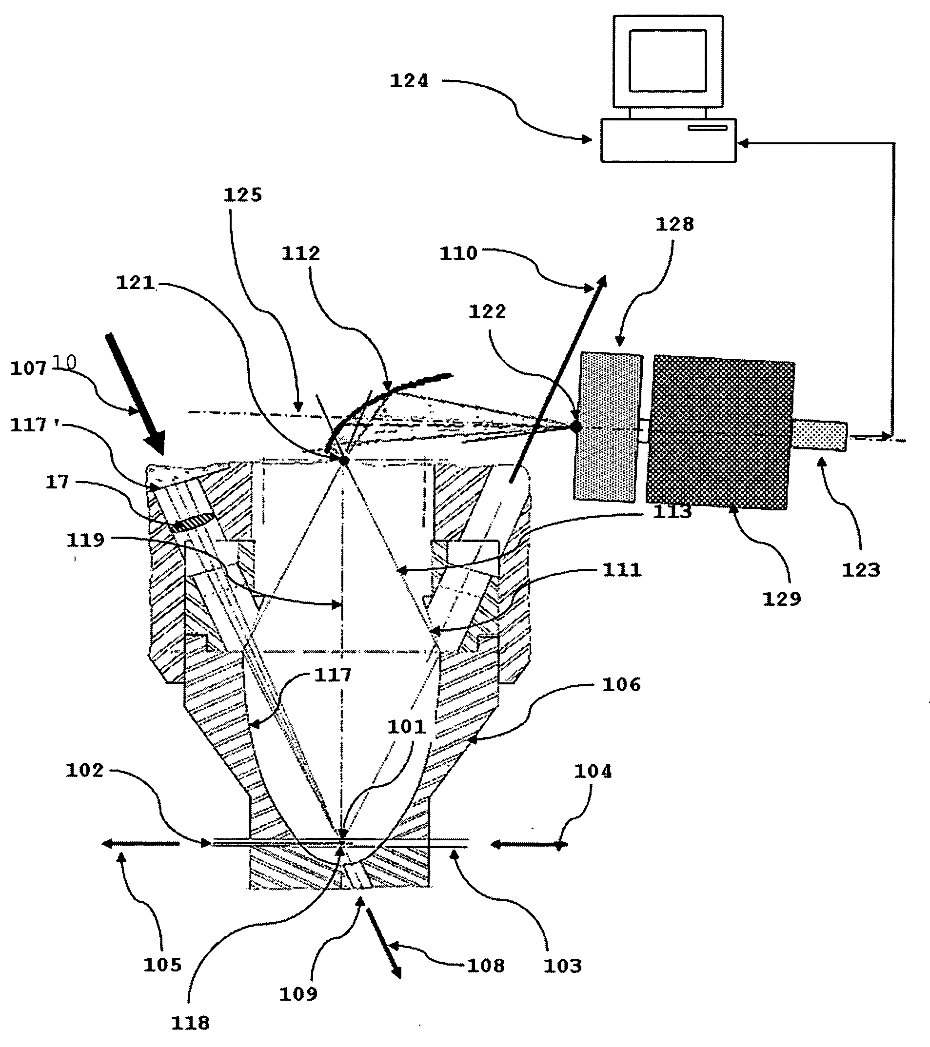
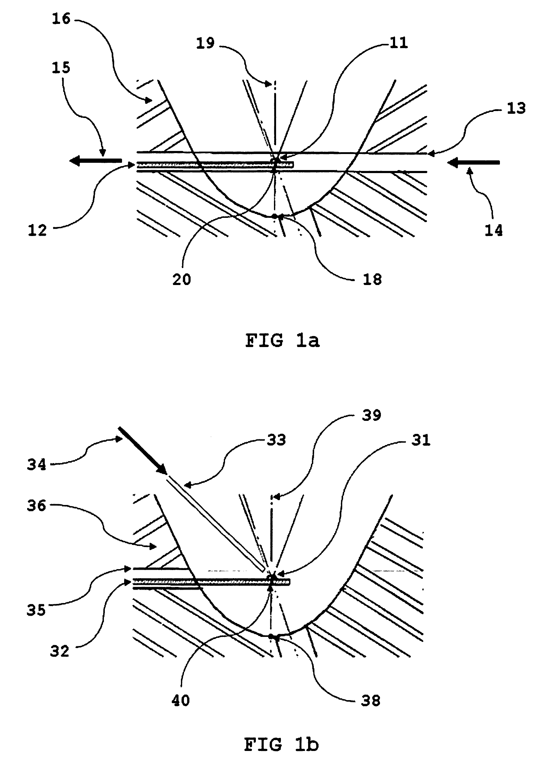
[0064]FIG. 1a is a detailed longitudinal cross-sectional view illustrating schematically the position of a tube containing an olfactory receptor in the device for this example.

[0065] An olfactory receptor 11 is positioned on a longitudinal support 12 made of silica which is transparent to UV and the support / olfactory receptor assembly is inserted in a tube 13 which is transparent to UV wavelengths (between 200 nm and 300 nm in particular) in such a way that a liquid or gas fluid can circulate between an input and an output indicated by arrows 14 to 15. The tube is inserted into an aluminium cell 16 which has a concave reflective surface 17 in ellipsoid form with an axis of revolution 19 for which one of the crowns is indicated at 18. In this, the tube crosses the elliptical cell perpendicularly to the axis 19 is such a way that the olfactory receptor is positioned at a focal point 20 relating to the crown 18 for the elliptical cell.

[0066]FIG. 1b is a detailed longitudinal cross-se...


PUM


Abstract

A medium is analysed for the search for an odorous biological molecule characteristic of a specific substance in an environment to be studied comprising the steps of: exposing a component containing at least one olfactory biological receptor, capable of selectively attaching the type of odorous molecule sought, to an atmosphere taken from the environment to be studied; irradiating that component by means of an incident laser radiation having a wavelength chosen in the ultraviolet close to the absorption wavelength for the olfactory receptor, to cause the excitation of a resonance Raman scattering in the irradiated component; and analysing the Raman spectrum obtained to determine whether or not it corresponds to the Raman spectrum of the olfactory receptor having attached an odorous molecule of the type sought in the atmosphere sampled, so as to identify any presence of the specific substance mentioned in the environment to be studied. The method applies particularly to the identification of toxic or hazardous substances in packaged products or objects or where access to them is difficult, for example during transit.

Description

TECHNICAL FIELD [0001] This invention relates to an optical method and device for studying and analysing chemical compounds and in particular biological compounds in a non-destructive mode. In particular, it may be applied for real-time monitoring of changes in the structure of an excited component as a function of its environment. PRIOR ART [0002] Certain continuous analysis methods for physico-chemical phenomena call on techniques based on sensors. A physico-chemical phenomenon may be a change in temperature, pressure, pH or concentration, etc. The element which provides the means for translating such a physico-chemical phenomenon and its variations into data which can be used electrically (or electronically) is usually referred to as a sensor. [0003] Biology is one of the scientific sectors which make great demand for measurement and detection technologies. Indeed it is often difficult to convert data of a biological origin into usable data which may take the form of an electric ...

Claims


Application Information

Patent Timeline
IPC IPC(8): G01J3/44
CPCG01J3/02G01J3/0216G01J3/10G01J3/44G01N21/0303G01N21/65
Inventor DE VANDIERE, BRUNODEBROCHE, CLAUDEGALIBERT, FRANCIS
Owner FLOWGENE
Why Eureka
Try Eureka