

Diesel particulate filters having ultra-thin catalyzed oxidation coatings
a technology of oxidation coating and particulate filter, which is applied in the direction of machine/engine, mechanical equipment, separation processes, etc., can solve the problems of affecting the health of people, affecting the performance of diesel engines, and presenting more severe problems
- Summary
- Abstract
- Description
- Claims
- Application Information
AI Technical Summary
Benefits of technology
Problems solved by technology
Method used
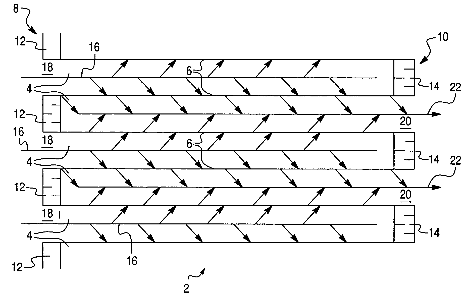
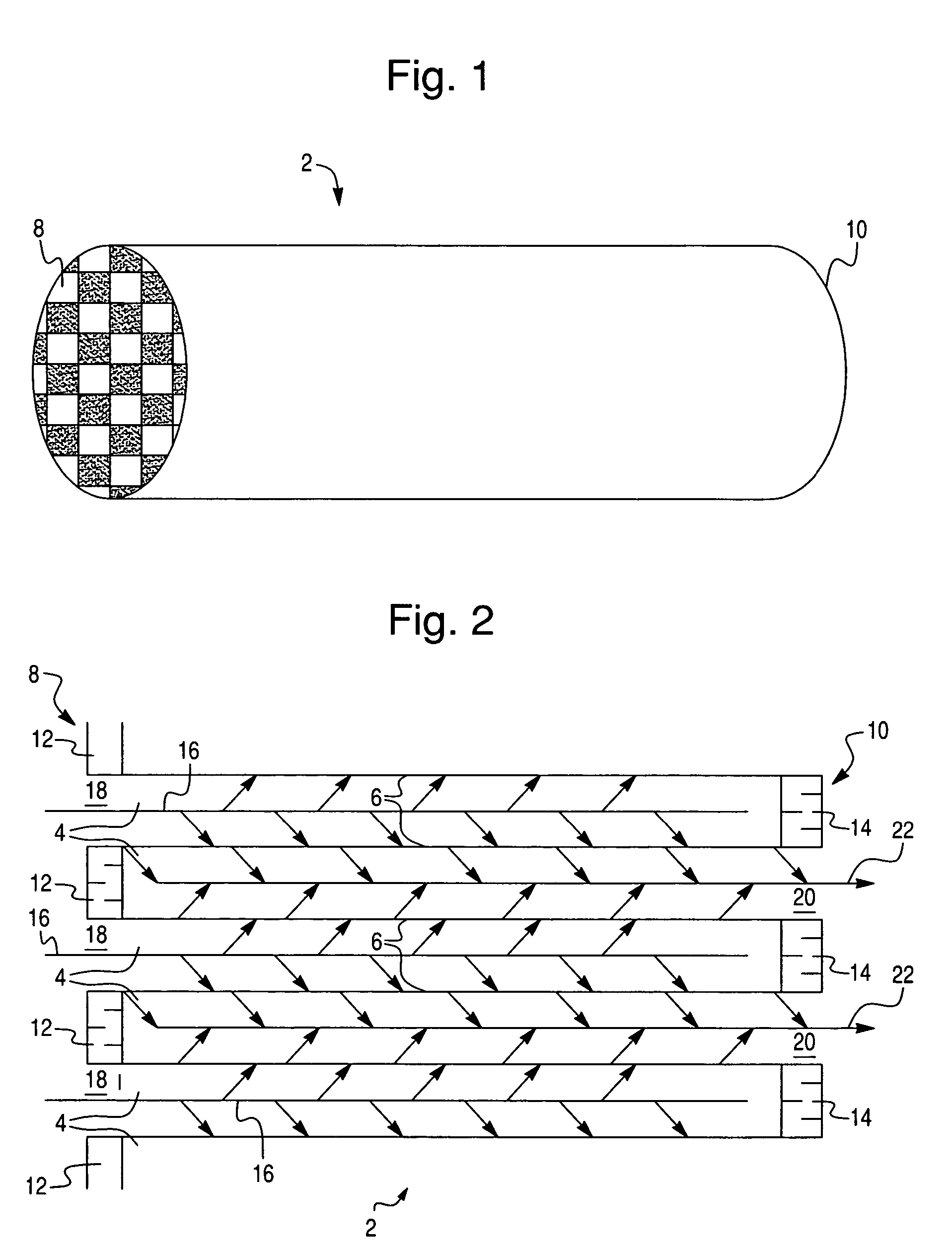
Image

Examples
example 1
Preparation of Sample A
[0076] Sample A was prepared by washcoating a 1″ diameter×3″ long SiC wall-flow substrate (58% porosity, 300 cell / square inch, 12 mil wall thickness). The wall-flow substrate was coated with a washcoat slurry containing 90 g / ft3 Pt, 0.6 g / in3 Siralox® Si / Al (approximately 1.5%silica and 98.5% alumina, obtained from Sasol North America, Houston, Tex.), 0.3 g / in3 sub-micron Ce / Zr composite (approximately 30% CeO2 and having an average crystallite size less than 0.5 micrometer, commercially available) and 0.05 g / in3 ZrO2. Pt amine salt was impregnated onto the Si / Al support to achieve the desirable loading. The Pt / Si / Al powder was then milled to reduce the particle size such that 90% of the particles were less than 5 micrometer. The Ce / Zr composite was added during the milling stage. An additional Zr component was added as a binder during the milling stage as zirconyl acetate sol. The pH of the resulting slurry was adjusted with acetic acid to achieve a value be...
example 2
Preparation of Sample B
[0077] Sample B was prepared by washcoating a 141 diameter×3″ long SiC wall-flow substrate (58% porosity, 300 cell / square inch, 12 mil wall thickness). The wall-flow substrate was coated with a washcoat slurry containing 90 g / ft3 Pt, 0.6 g / in3 sub-micron alumina (commercially available), 0.3 g / in3 sub-micron Ce / Zr composite (approximately 30% CeO2 and having an average crystallite size less than 0.5 micrometer, commercially available) and 0.05 g / in3 ZrO2. The sub-micron alumina was already dispersed in water by the manufacturer and had an average particle size of 40 nanometers. The washcoat slurry was free of precious metal, and the washcoat was applied by immersing the substrate into the slurry. The excess slurry was blown-out by using an air knife. The sample was dried at 110° C. for 2 hours then calcined in an oven at 450° C. for 1 hour. The resulting sample was then immersed into Pt amine salt solution to pick up desirable amount of Pt. This sample was th...
example 3
Preparation of Sample C
[0078] Sample C was prepared by washcoating a 1″ diameter×3″ long SiC wall-flow substrate (58% porosity, 300 cell / square inch, 12 mil wall thickness). The wall-flow substrate was coated with a washcoat slurry containing 90 g / ft3 Pt, 0.6 g / in3 Siralox® Si / Al (approximately 1.5% silica and 98.5% alumina, obtained from Sasol North America (Houston, Tex.)), 0.3 g / in3 sub-micron alumina (commercially available), 0.3 g / in3 Ce / Zr composite (containing about 30% CeO2 and having an average crystallite size around 5 micrometers, commercially available) and 0.05 g / in3 ZrO2. The sub-micron alumina was already in a dispersed form and was coated on the substrate alone as a pre-coat. The sub-micron alumina was then calcined at 450° C. for 1 hour. The second slurry was prepared as follows. The Pt amine salt was impregnated onto the Siralox® support to achieve the desirable loading. The Pt / Siralox® Si / Al powder was then milled to reduce the particle size such that 90% of the ...
PUM
| Property | Measurement | Unit |
|---|---|---|
| size | aaaaa | aaaaa |
| porosity | aaaaa | aaaaa |
| concentrations | aaaaa | aaaaa |
Abstract
Description
Claims
Application Information