Optically fluorescent nanoparticles

a technology of fluorescent nanoparticles and nanoparticles, applied in the field of optically fluorescent nanoparticles, can solve problems such as excess charge, and achieve the effects of enhancing the sensitivity of in vivo imaging, enriching tumour tissue, and high dye concentration for detection

Inactive Publication Date: 2007-05-10
SCHERING AG
View PDF0 Cites 40 Cited by
  • Summary
  • Abstract
  • Description
  • Claims
  • Application Information

AI Technical Summary

Benefits of technology

[0125] The nanoparticles of the present invention are particularly useful for in vivo and in vitro diagnosis. After application of nanoparticles of the present invention to a live organism, they particularly enrich in tumour tissue. This is due to passive and active targeting effects. Once located in targeted tissue, the inventive nanoparticles are taken up by tissue cells via endocytosis. Following this cellular incorporation, disaggregation into the nanoparticle's components occurs resulting in “free” optically fluorescent agent. From in vitro experiments using blood plasma it has been concluded that disaggregation is supported by changes of ionic concentration and the presence of charged blood compounds, e.g. albumin or salts. Intracellular disaggregation is possibly proceeded by the “proton sponge” effect. Furthermore, disaggregation of the nanoparticle occurs independently of any polymer degradation resulting in rapid release of the optically fluorescent agent and providing a high dye concentration for detection.
[0126] Thus, the nanoparticles of the present invention selectively enrich in pathologically altered tissue due to passive and active targeting and, simultaneously, the sensitivity of in vivo imaging is enhanced since the fluorescent signal of intracellularly free optically fluorescent dye is increased.

Problems solved by technology

In one embodiment, the ratio of total polyelectrolyte charge and total optically fluorescent agent charge results in a charge surplus.

Method used


Image

  • Optically fluorescent nanoparticles
  • Optically fluorescent nanoparticles
  • Optically fluorescent nanoparticles

Examples


example 1

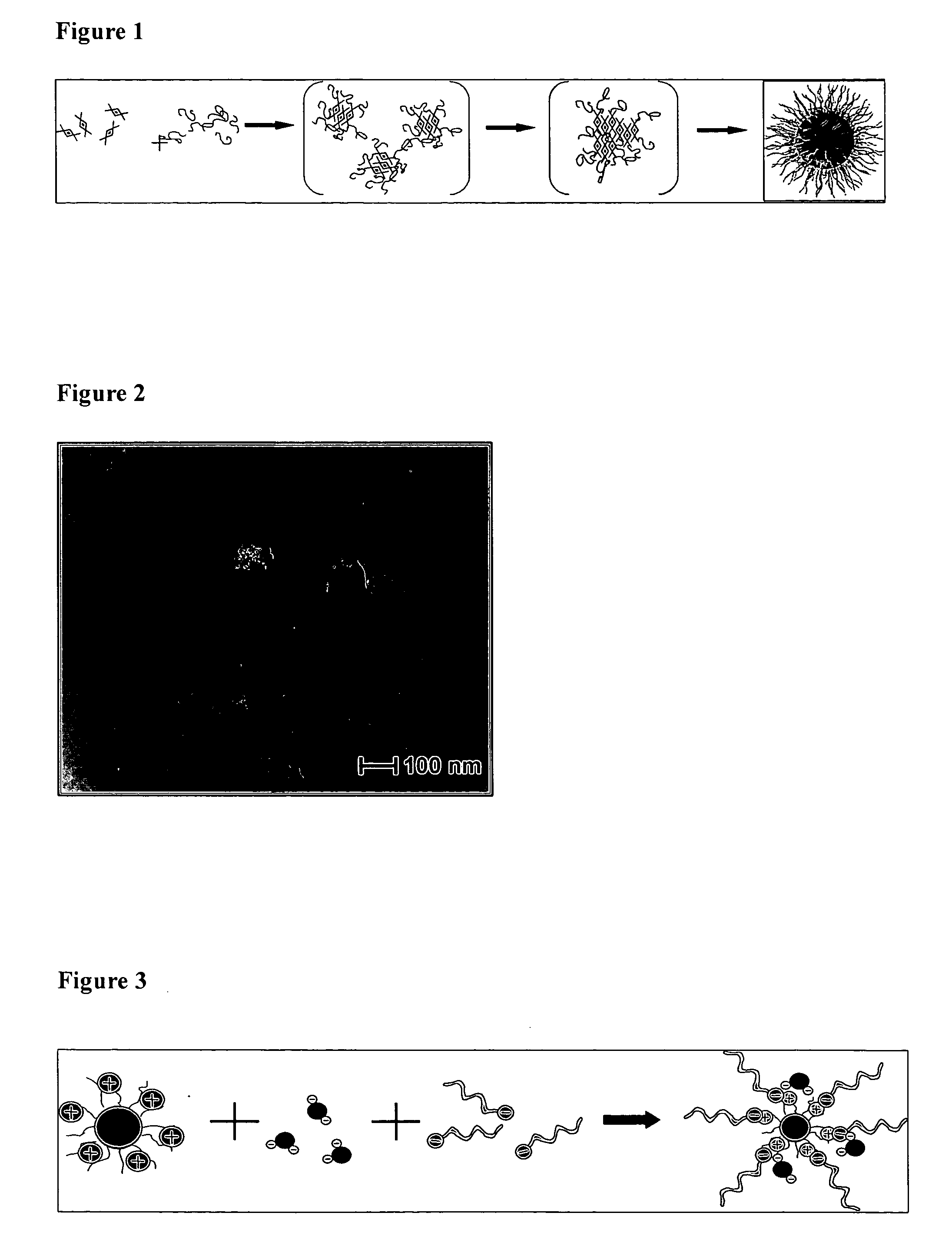
Optically Fluorescent Nanoparticles Based on PEI

(a) Preparation of PEI Based Nanoparticles

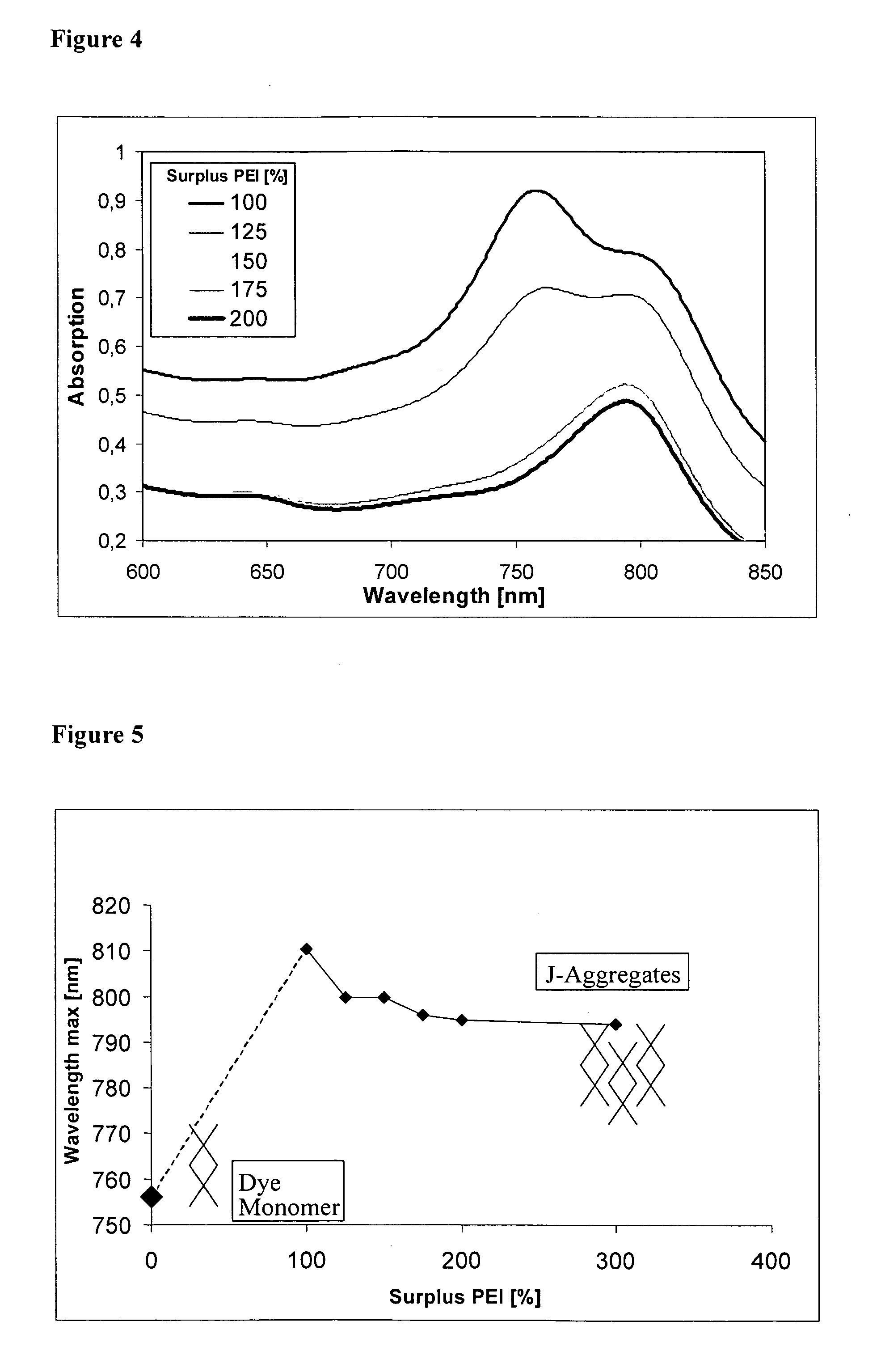
[0147] An aqueous solution of 0.1% (w / v) PEI (1.8, 10, 70, or 750 kDa) is gently stirred, and an aqueous solution of 0.02% (w / v) TITCC is instantly added. This composition is further agitated at about 4° C. for about 30-45 minutes under UV protection. The aggregation progress is monitored by UV-Vis spectra starting from 900 nm down to 600 nm. TITCC dye has been shown to possess fluorescent activity when incorporated into PEI nanoparticles, and aggregate formation can be monitored on the basis of a shift of the UV-Vis spectrum (FIG. 4) The nanoparticle dispersion is concentrated by ultrafiltration and lyophilised after addition of a cryoprotector such as mannitol or lactose.

[0148] As shown in FIG. 4, the complete formation of dye molecules to J-aggregated had taken place in case of 150, 175, and 200% surplus of PEI. This is confirmed by the absence of the starting wavelength of 756 nm of the...

example 2

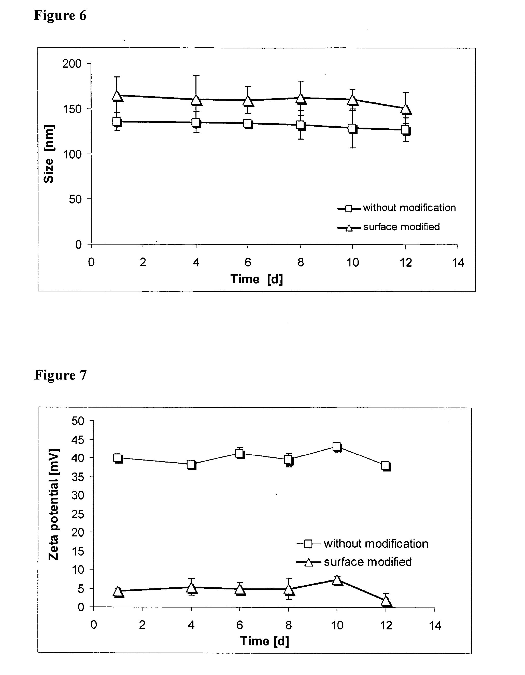
Nanoparticles Based on Protamine Sulphate

[0159] Cationic protamine sulphate is widely used in vivo as heparin antagonist. Thus, nanoparticles comprising protamine sulfate as cationic polyelectrolyte are superior due to experienced less toxicity.

example 3

Nanoparticles Based on P(DMAPMAM)

[0160] A solution of 0.1% P(DMAPMAM) in water / acetone (10:1. by volume) is gently stirred while a solution of 0.02% TITCC is added instantly. Under further agitation, formation of the aggregates takes place while acetone is removed.


PUM

PropertyMeasurementUnit
hypsochromicaaaaaaaaaa

Abstract

The present invention refers to nanoparticles having optically fluorescent activity. In more detail, the invention refers to a nanoparticle matrix comprising a co-aggregate of at least one charged polyelectrolyte and at least one oppositely charged active agent, wherein the active agent is a hydrophilic optically fluorescent agent, and the invention further refers to a nanoparticle comprising said nanoparticle matrix. Optionally, the nanoparticle is surface modified. The invention also refers to a method for preparing said nanoparticle, and to a method of surface modification. Furthermore, the invention refers to uses of said nanoparticle in vitro and in vivo, and to methods for in vitro and in vivo diagnosis.

Description

[0001] This application claims the benefit of the filing date of U.S. Provisional Application Ser. No. 60 / 713,331 filed on Sep. 2, 2005, which is incorporated by referenced herein.[0002] The present invention refers to nanoparticles having optically fluorescent activity. In more detail, the present invention refers to a nanoparticle matrix comprising a co-aggregate of a polyelectrolyte and a hydrophilic optically fluorescent agent, and to a nanoparticle comprising said nanoparticle matrix. Optionally, the nanoparticle is surface modified. The present invention also refers to a method for preparing said nanoparticle and to a method of surface modification. The present invention further refers to uses of said nanoparticle in vitro and in vivo, and to methods for in vitro and in vivo diagnosis. BACKGROUND OF THE INVENTION [0003] For diagnostic purposes, optically fluorescent dyes are particularly useful since low-energy fluorescent light is biologically safe compared to, for example, h...

Claims


Application Information

Patent Timeline
Patent Type & Authority Applications(United States)
IPC IPC(8): A61K49/00
CPCA61K9/5138A61K9/5146A61K49/0032A61K49/0034A61K49/0052A61K49/0054A61K49/0056A61K49/0093B82Y15/00G01N33/533G01N33/582G01N33/588
Inventor FISCHER, KATRIN CLAUDIAGENERAL, SASCHALICHA, KAI
Owner SCHERING AG
Why Eureka
Try Eureka