Optical resonance analysis unit

Inactive Publication Date: 2007-05-17
GE HEALTHCARE BIO SCI CORP
View PDF8 Cites 66 Cited by
  • Summary
  • Abstract
  • Description
  • Claims
  • Application Information

AI Technical Summary

Benefits of technology

[0038] Another advantage of the most preferred fluidics system described herein is the capability for “on the fly” sample loading which is made possible by two separate pumps, one driving the buffer solution and one driving the sample, which allows the user to prepare the sample while the buffer is running through the system. In many instances, it is advantageous using the present instrument, to allow buffer solution to run separately through the system for a few minutes or longer in order to establish a baseline. In addition, in cases where sample loading is time-dependent, for example where the time between sample preparation, mixing, etc., and loading is required to be short due to sensitive samples that may degrade over time and/or with changes in temperature, independent buffer and sample fluidic paths allow samples to be prepared and loaded just minutes or even seconds before injection and introduction onto the sensor. Sample recirculation as described above is also advantageous for samples with particularly slow on-rates (i.e., low association constants) as it allows the samples to keep (re)cycling through the system for sufficient lengths of time to observe sufficient response to calculate accurate association constants kON.
[0039] In addition, if a reaction proceeds slowly, then recirculation is particularly advantageous in that small amounts of sample may be continually recontacted with the sensor surface, whereas if this option were not available, the user would have to acquire much larger amounts of a sample, which may be difficult or prohibitively costly, if not impossible. This “endless supply” of re-circulating sample thus provides sufficient flexibility in both the contact time and flow rate to allow for the monitoring of very slow or mass transport-limited reactions.
[0040] The use of a 4-way valve is particularly advantageous in the fluidics system of the present invention because: (1) it maintains the integrity of the concentrations of the buffer and samples as the system is simultaneously running and preparing for sample injection and, (2) the location of the 4-way valve, i.e., immediately adjacent the sensor, minimizes any mixing of the buffer/sample interface.
[0041] The fluidics system of the present invention also includes a “bubble blast” high velocity pulsating flow driven by a syringe pump. When putting a new flow cell (containing a new sensor chip) into operation, it is commonly the case that air bubbles remain in the cell gap after filling with buffer. Air bubbles may also inadvertently be introduced during sample switching and other fluid transport operations. These bubbles prevent accurate measurements of the binding reactions on affected ROIs and must be removed, which can be difficult, particularly where the dimensions of the flow cell containing the sensor are

Problems solved by technology

However, current grating coupled SPR methods employing angle scanned array imaging to measure many samples in parallel share certain disadvantages with other angle scanned optical resonance sensor methods, including Kretchmann SPR imaging approaches.
Many of the problems associated with angle scanned array SPR are related to system optics and the fact that SPR array imaging requires a relatively high numerical aperture imaging system to accommodate the range of illumination angles involved in an SPR scan, but for each individual exposure or image frame during an angle scan the light is highly concentrated into a small portion of the full aperture pupil.
Such aberrations are common in conventional high numerical aperture imaging systems but are generally tolerated, merely causing loss of contrast or resolution when all aperture angles are present simultaneously.
However, in array SPR they pose a serious problem since highly accurate reflectance measurements must be made at carefully defined locations on the sensor chip surface as a function of illumination angle.
However, such post-event data processing compensation for the walking effect is a less preferable solution to the generation of more accurate data in the first place.
Another problem associated with the aforementioned severe instantaneous underfilling of the aperture pupil in current SPR array instruments is the phenomenon of “hot spots” or image flare caused by multiple reflections between the various optical surfaces, particular

Method used


Image

  • Optical resonance analysis unit
  • Optical resonance analysis unit
  • Optical resonance analysis unit

Examples


Embodiment Construction

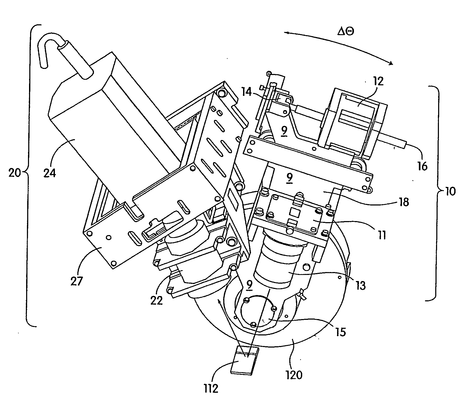
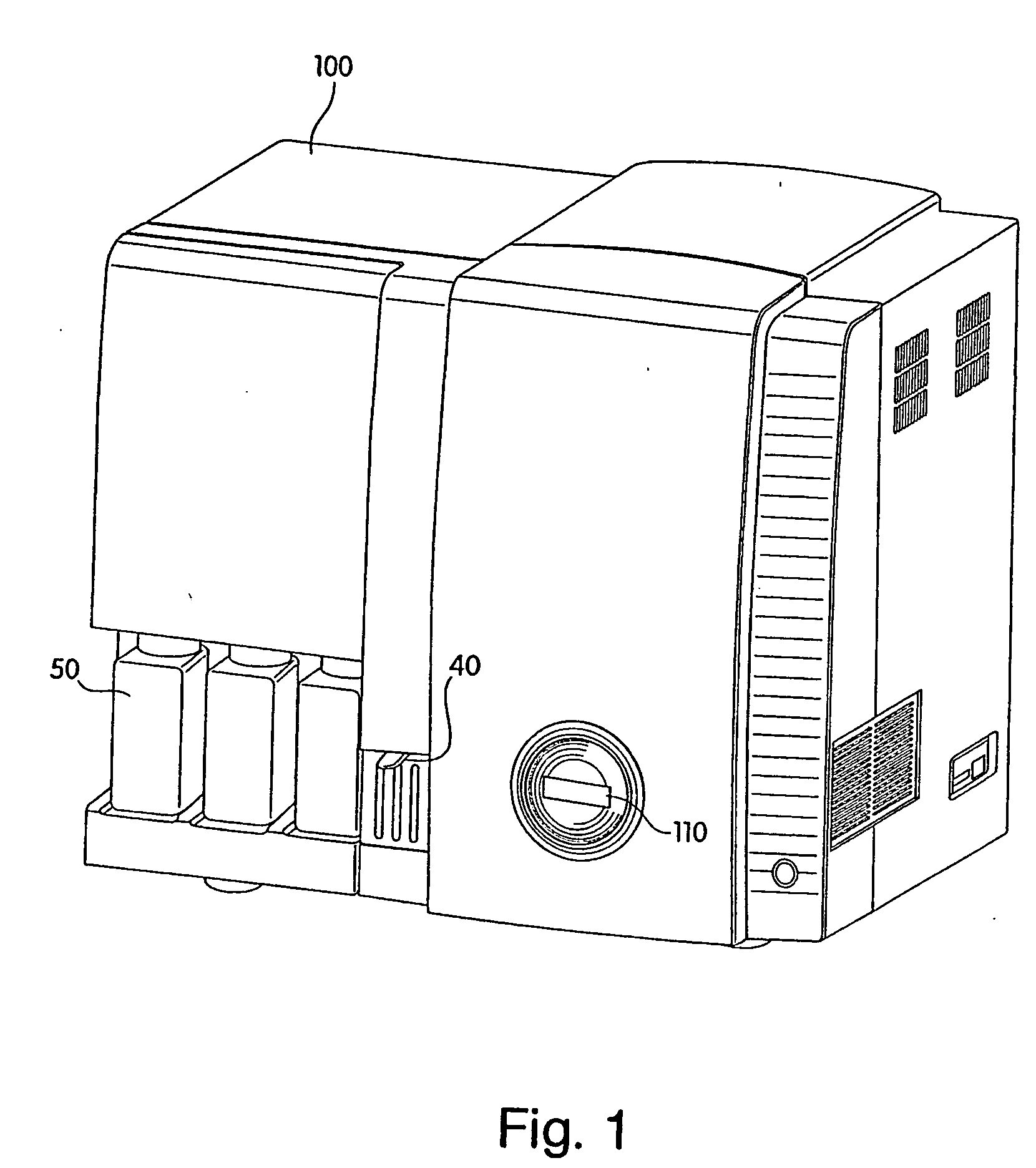
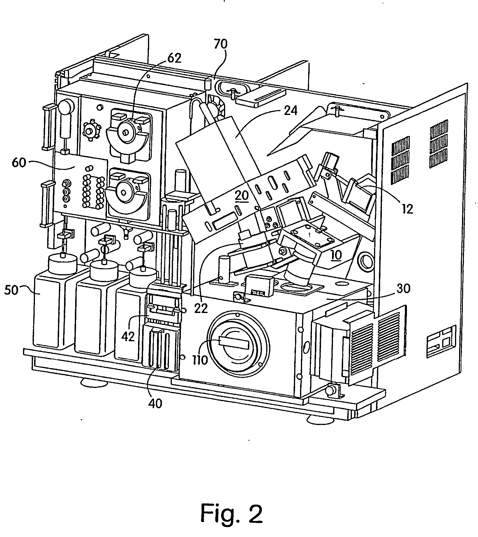
[0052] The present invention is directed to an improved optical resonance analysis instrument for use especially in grating coupled surface plasmon resonance (GCSPR) capable of simultaneous measurement of an array of reaction sites. In particular, the present invention combines a number of features which, in addition to enabling real-time analysis of up to thousands of molecular binding interactions, also provides improvements in controlling reaction parameters involving system fluidics, temperature control, sensor scanning, and data collection and analysis from the scanned sensor.

[0053] The analysis unit may be fully automated and have all optical scanning operations controlled or implemented automatically by software included with the unit. Essentially, once the buffers, sample, and sensor are loaded into the unit, the user may enter the experimental parameters, e.g., time, temperature, fluid flow rate, etc., into a computer connected to the unit, and the unit can be programmed t...


PUM


Abstract

An optical analysis unit especially suitable for performing grating coupled surface plasmon resonance (SPR) imaging features a pivoting light source capable of scanning through a range of angles of incident light projected onto a stationary target sensor, such as an SPR sensor. The reflected image from the illuminated sensor is detected, e.g., by a CCD camera and the image and angular scan data are processed, for example by a fitting algorithm, to provide real time analysis of reactions taking place on the surface of the sensor.

Description

CROSS-REFERENCE TO RELATED APPLICATIONS [0001] This application claims priority to U.S. Provisional Application 60 / 492,061 and 60 / 492,062, both filed Aug. 1, 2003, the disclosures of which are incorporated herein by reference.FIELD OF THE INVENTION [0002] This invention relates generally to optical resonance analysis systems. Specifically, the invention relates to an improved instrument for conducting grating coupled surface plasmon resonance imaging utilizing illumination and detection systems for the real-time analysis of multiple reactions taking place on the surface of a sensor array. BACKGROUND OF THE INVENTION [0003] The basic principle of operation of grating-coupled surface plasmon resonance (GCSPR) takes advantage of surface charge vibrations created when light of a certain wavelength strikes a metal surface. For example, a sensor chip comprised generally of a plastic optical grating coated with a thin (˜80 nm) layer of highly reflective metal such as gold is spotted with a...

Claims


Application Information

Patent Timeline
IPC IPC(8): G01N21/55
CPCG01N21/553
Inventor TRACY, DAVID H.BROCKMAN, JENNIFER M.FERRARA, KEITH S.SHENKER, MARTINKERSTEN, ROBERTCOHEN, STEVEN E.BODLEY, GARYTUXBURY, PATRICKHETHERINGTON, PAULPICOZZA, ENRICO
Owner GE HEALTHCARE BIO SCI CORP
Why Eureka
Try Eureka