Plastic chip for PCR having on-chip polymer valve
- Summary
- Abstract
- Description
- Claims
- Application Information
AI Technical Summary
Benefits of technology
Problems solved by technology
Method used
Image

Examples
example 1
Fabrication of Plastic Chip for PCR
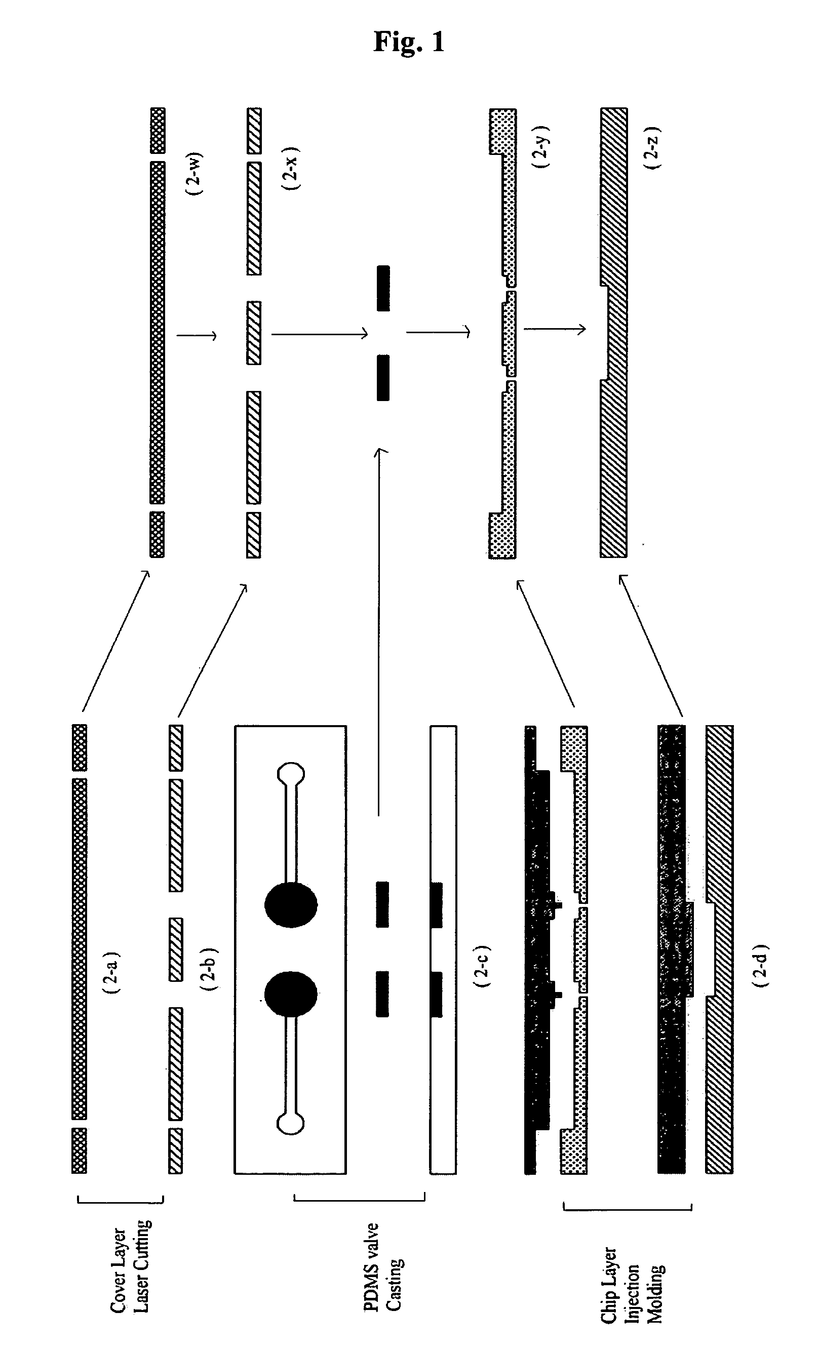
[0029] A plastic chip is fabricated through three steps of cutting of a cover layer, casting of a PDMS valve and injection molding of a chip layer (FIG. 1).
[0030] As shown in FIG. 1, the uppermost cover layer 2-w was formed using a polymer film made of the same material as those of a 0.1 mm thick intermediate plastic layer 2-y and a bottom plastic layer 2-z, and the fluid inlet and outlet thereof were formed by laser cutting 2-a. A second layer 2-x serving to bond the uppermost cover layer 2-w with an intermediate plastic layer 2-y was fabricated of a double-sided adhesive tape, which was formed of a silicon-based material and thus maintained strong bonding properties even at high temperatures, and the fluid inlet and outlet thereof were formed by laser cutting 2-b. An intermediate plastic layer 2-y and a bottom plastic layer 2-z were formed by polymer injection molding 2-d. As shown as “2-d ” in FIG. 1, fluid passageways connecting a PCR chamber...
example 2
DNA Temperature Cycling Using Inventive Plastic Chip for PCR
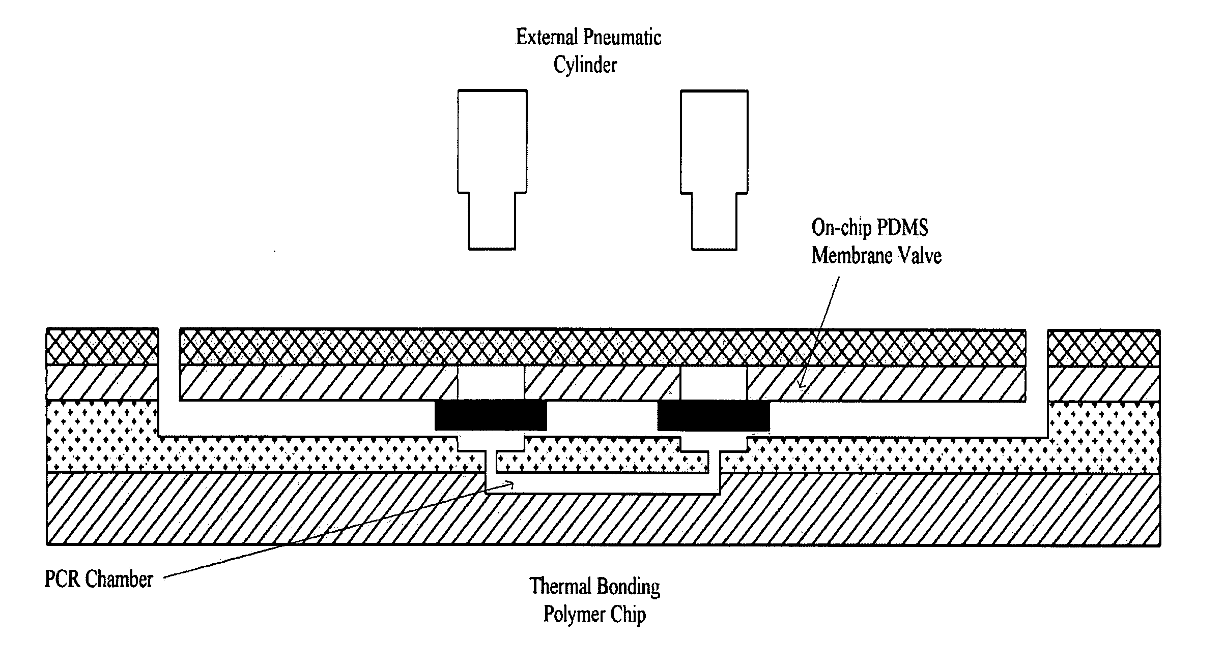
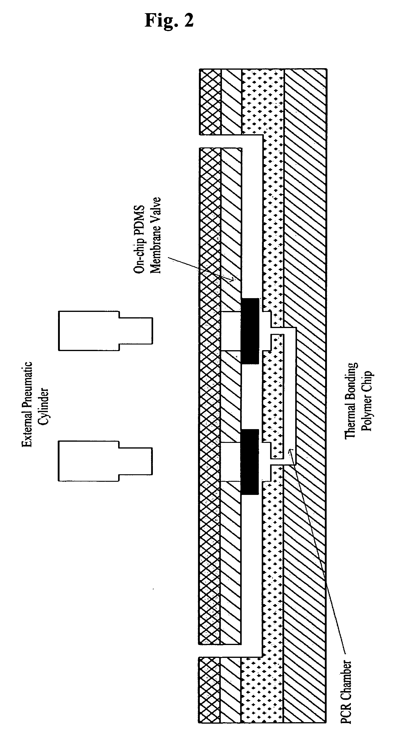
[0031] A mixture solution for PCR was added into the plastic chip fabricated in Example 1, and an external film heater and an air cooling fan were disposed on the bottom of the PCR chamber. Then, the PDMS on-chip valve was pressed with a pneumatic cylinder to conduct PCR temperature cycling. A thermocouple was attached to the film heater, and another thermocouple was also inserted into the PCR chamber. These thermocouples were used to measure the surface temperature of the film heater and the temperature inside the PCR chamber during the PCR temperature cycling (FIG. 3). As can be seen in FIG. 3, because the heat conductivity of the polymer was similar to the heat conductivity of air, there was an average temperature difference of 4-8° C. due to a PCR chamber thickness of 0.5 mm. In this Example, a chip design was used, in which the film heater was mounted on the outer surface of the PCR chamber, and thus the outer surface...
example 3
Amplification of Plasmid DNA Using Inventive Plastic PCR Chip
[0033] Using the temperature cycling plastic PCR chip of Example 1, mounted with the on-chip polymer valve, and the PCR temperature cycling system of Example 2, comprising the film heater and the cooling fan, a 1-kb fragment of a pET21a vector (Novagen, USA) was amplified with the following primers.
ManhsKAM Nde (forward) primer (SEQ ID NO:1):5′-AGAGAGCATATGCGTATTTTAACTCAAAATAACCCA-3′ManhsKAM EcoR (reverse) primer (SEQ ID NO:2):5′-AGAGAATTCTTAACCGCCGTAAAGGGTCTTATTCGG-3′
[0034] The PCR amplification was performed in the following conditions: pre-denaturation for 5 minutes; and then 30 cycles, each consisting of denaturation for 30 sec, annealing for 30 sec and extension for 30 sec; followed by post-extension for 5 minutes (FIG. 3).
[0035] As a result, it could be found that the PCR amplification was made on the inventive plastic chip for PCR at the same level as conducted on the prior bench top machine using tubes (FIG. 4)...
PUM
 Abstract
Description
Claims
Application Information
 - Generate Ideas
- Intellectual Property
- Life Sciences
- Materials
- Tech Scout
- Unparalleled Data Quality
- Higher Quality Content
- 60% Fewer Hallucinations
Browse by: Latest US Patents, China's latest patents, Technical Efficacy Thesaurus, Application Domain, Technology Topic, Popular Technical Reports.
© 2025 PatSnap. All rights reserved.Legal|Privacy policy|Modern Slavery Act Transparency Statement|Sitemap|About US| Contact US: help@patsnap.com