

Film, film forming composition and electronic device having the film
- Summary
- Abstract
- Description
- Claims
- Application Information
AI Technical Summary
Benefits of technology
Problems solved by technology
Method used
Image


Examples
example 1
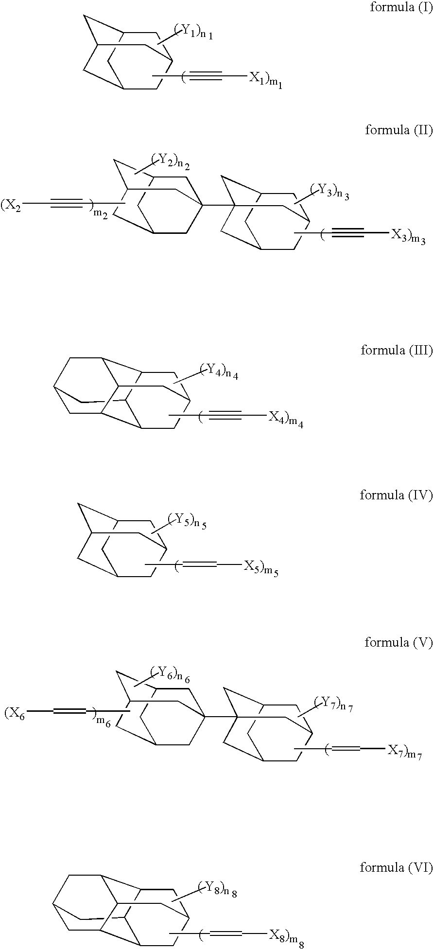
[0128] In accordance with the synthesis process as described in Macromolecules, 24, 5266-5268(1991), 4,9-diethynyldiamantane was synthesized. Under a nitrogen gas stream, 2 g of 4,9-diethynyldiamantane, 0.22 g of dicumyl peroxide (“PERCUMYL D”, trade name; product of NOF) and 10 ml of t-butylbenzene were polymerized by stirring them for 7 hours at an internal temperature of 150° C. After the reaction mixture was cooled to room temperature, 60 ml of isopropyl alcohol was added. The solid thus precipitated was collected by filtration and washed with isopropyl alcohol, whereby 0.8 g of polymer (A) having a mass-average molecular weight of about 15000 was obtained.
[0129] The solubility of Polymer (A) in cyclohexanone was 15 mass % or greater at 25° C.
[0130] A coating solution was prepared by completely dissolving 1.0 g of Polymer (A) in 10 g of cyclohexanone. The resulting solution was filtered through a 0.1 μm filter made of tetrafluoroethylene, followed by spin coating on a silicon ...
example 2
[0136] Under a nitrogen gas stream, 2 g of 4,9-diethynyldiamantane, 0.8 g of 1,1′-azobis(cyclohexane-1-carbonitrile (“V-40”, trade name; product of Wako Pure Chemicals) and 10 ml of dichlorobenzene were polymerized by stirring them for 8 hours at an internal temperature of 100° C. After the reaction mixture was cooled to room temperature, 100 ml of methanol was added. The solid thus precipitated was collected by filtration and washed with methanol, whereby 1.0 g of Polymer (B) having a mass-average molecular weight of about 10000 was obtained. The solubility of Polymer (B) in cyclohexanone was 15 mass % or greater at 25° C.
[0137] A coating solution was prepared by completely dissolving 1.0 g of Polymer (B) in 10 g of cyclohexanone. The resulting solution was filtered through a 0.1 μm filter made of tetrafluoroethylene, followed by spin coating on a silicon wafer, whereby a film was obtained.
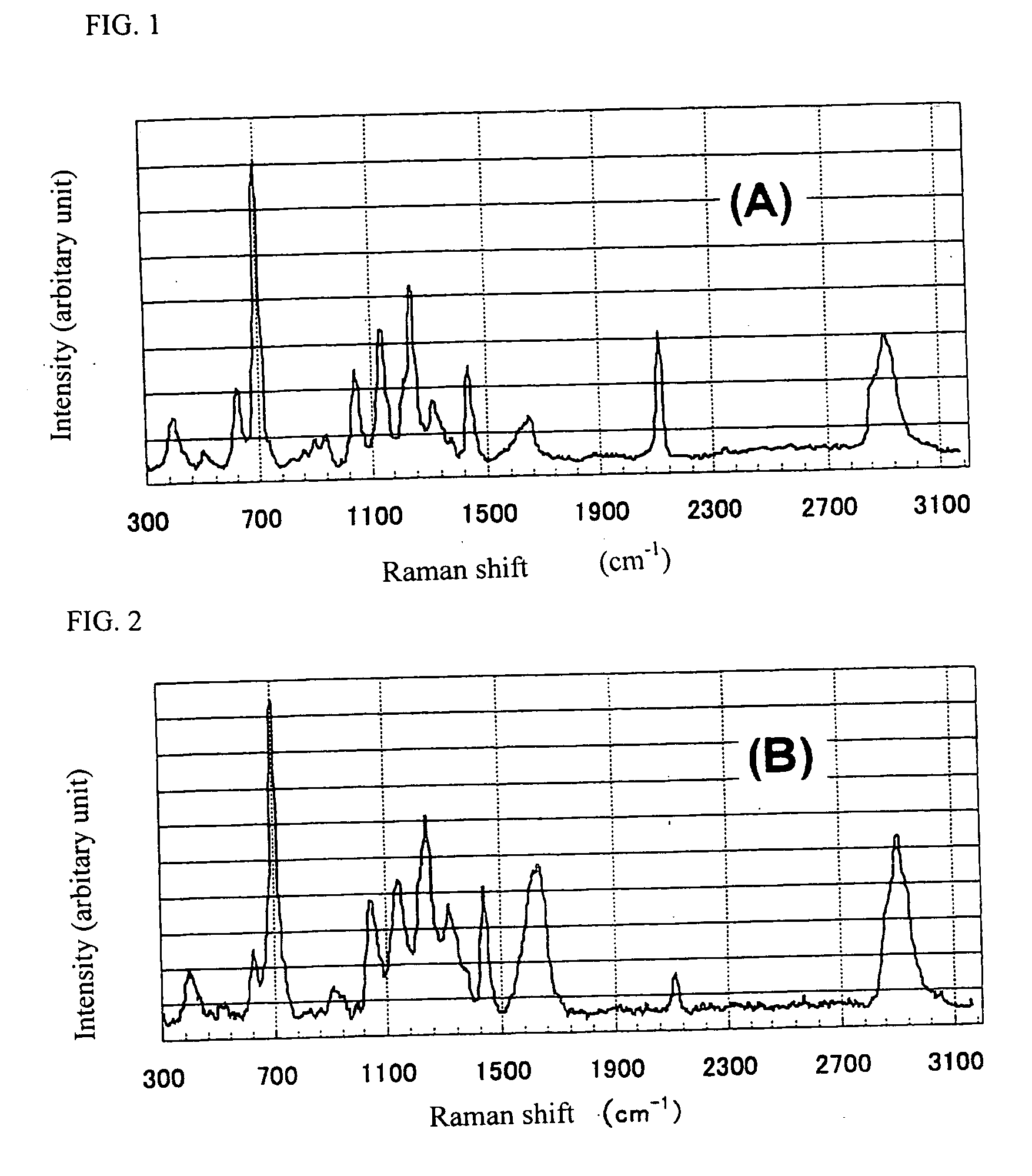
[0138] A portion of the film was chipped off and subjected to Raman spectroscopy in the sam...
example 3
[0141] In a similar manner to Example 1 except for the use of 1,6-diethynyldiamantane instead of 4,9-diethynyldiamantane, 0.9 g of Polymer (C) was synthesized. As a result of GPC measurement, the polymer had a mass-average molecular weight of about 20000.
[0142] The solubility of Polymer (C) in cyclohexanone was 15 mass % or greater at 25° C.
[0143] A 10 mass % solution of the polymer in cyclohexanone was prepared and filtered through a 0.2 μm filter made of TFE, followed by spin coating on a silicon wafer, whereby a film was obtained.
[0144] A portion of the film was chipped off and subjected to Raman spectroscopy in the same way as in Example 1. As a result, in a Raman shift range of from 300 to 3100 cm−1, the highest intensity peak existed at 750 cm−1 and its peak intensity was about 2000. A peak attributable to —C═C— existed at 1655 cm−1 and its peak intensity was about 500. The film was baked at 400° C. for 60 seconds in a furnace purged with nitrogen. As a result, a 0.5-μm thi...
PUM
| Property | Measurement | Unit |
|---|---|---|
| Temperature | aaaaa | aaaaa |
| Percent by mass | aaaaa | aaaaa |
| Length | aaaaa | aaaaa |
Abstract
Description
Claims
Application Information