Nanostructured superalloy structural components and methods of making

a superalloy and nanostructure technology, applied in the field of superalloys, can solve the problems of affecting the quality of nanostructured alloys,

Inactive Publication Date: 2007-07-05
GENERAL ELECTRIC CO
View PDF9 Cites 27 Cited by
  • Summary
  • Abstract
  • Description
  • Claims
  • Application Information

AI Technical Summary

Benefits of technology

[0009] A method of manufacturing a nanostructured superalloy-containing structural component generally includes introducing dislocations into a superalloy particle matrix effective to form new grain boundaries within a plurality of superalloy particles, wherein the grains are nanostructured; introducing hard phase dispersoid nanoparticles at a plurality of grain boundaries of the superalloy particles effective to pin the grain boundaries; and thermo-mechanically processing the superalloy particle matrix and hard phase dispersoid nanoparticles to form the nanostructured superalloy-containing structural component.

Problems solved by technology

Unfortunately, nanostructured alloys, like their larger-scale counterparts, undergo the processes of recovery, recrystallization, and / or grain growth upon heating.
In fact, owing to their non-equilibrium nature, nanoscale grains are more susceptible to these processes than are micrometer scale grains.
Consequently, when thermo-mechanically processing nanostructured alloys into a shaped article, the nanostructure and, consequently, the superior properties are often lost.
The introduction of hard phase dispersoid nanoparticles during the processing of the alloys presents a major technical challenge.
Unfortunately, these processes fail to produce a homogeneous distribution of nanoparticles in the alloy matrix, especially for large components.
In addition, the loading of the hard phase dispersoid particles in the alloy composites is frequently limited to less than 2 volume percent.
Thus, current processes are unable to produce nanostructured alloys having a sufficiently high enough loading of nanoparticle dispersoids to provide increased strength to the alloy or article made therefrom.

Method used


Image

  • Nanostructured superalloy structural components and methods of making
  • Nanostructured superalloy structural components and methods of making
  • Nanostructured superalloy structural components and methods of making

Examples


example 1

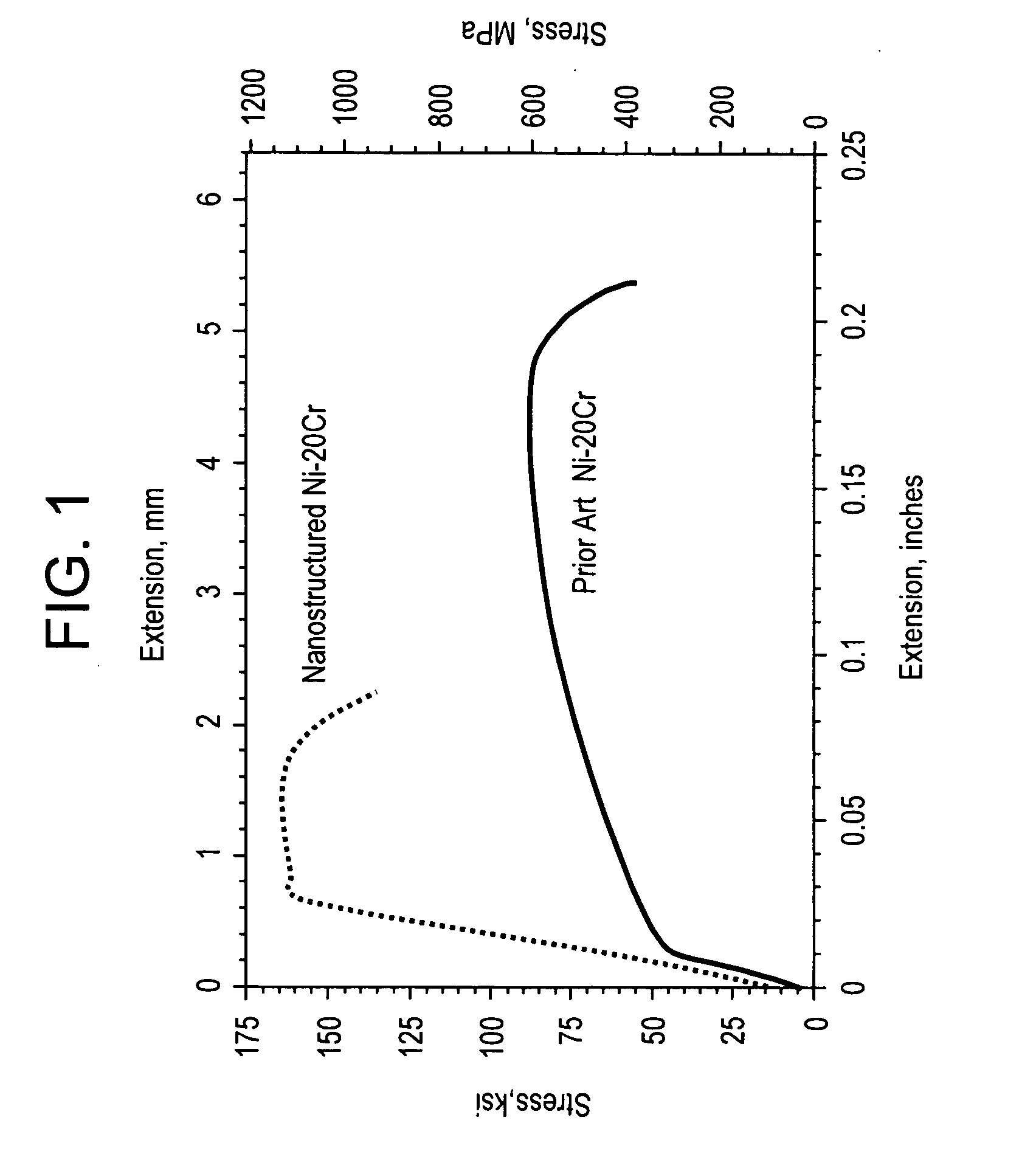
[0036] An alloy, comprising nickel and about 20 wt % Cr (Ni—20Cr), was produced by melting and forging. The average grain diameter after heat treatment of this prior-art material is approximately 64 micrometers (μm). The same base alloy composition was produced as a powder, cryomilled in liquid nitrogen, consolidated, and heat-treated. The grain size after heat treatment of this novel material was about 64 nm. Room temperature tensile tests were conducted on both materials. FIG. 1 illustrates the tensile curves for the two materials. The ultimate tensile strength of the prior art micrometer-scale material was about 87 kilopounds per square inch (ksi), or 600 MegaPascals (MPa), while the ultimate tensile strength of the nanostructured alloy was about 162 ksi (1117 MPa). This represented an 86% higher tensile strength in the alloy produced by the methods disclosed herein.

example 2

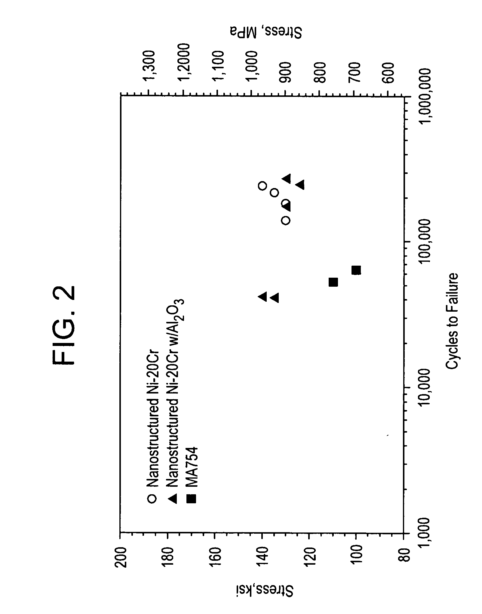
[0037] A nanostructured Ni—20Cr sample was prepared as described in Example 1, except that, in addition, a plurality of Al2O3 dispersoid nanoparticles were introduced prior to cryomilling. FIG. 3 presents representative scanning electron microscope images of this superalloy composition.

[0038] The fatigue properties of 1) this nanostructured Ni—20Cr superalloy, which had dispersoid nanoparticles introduced at the grain boundaries both ex-situ and in-situ (designated “nanostructured Ni—20Cr w / Al2O3”), 2) a nanostructured Ni—20Cr superalloy prepared according to Example 1, which only had dispersoid nanoparticles introduced at the grain boundaries in-situ (designated “nanostructured Ni—20Cr”), and 3) a known Ni-20Cr superalloy, obtained from Special Metals Corporation under the trade designation INCONEL MA754 (designated “MA754”) were studied. FIG. 2 displays the results of the high-cycle fatigue properties of these three samples. Data is presented for five samples of the nanostructure...

example 3

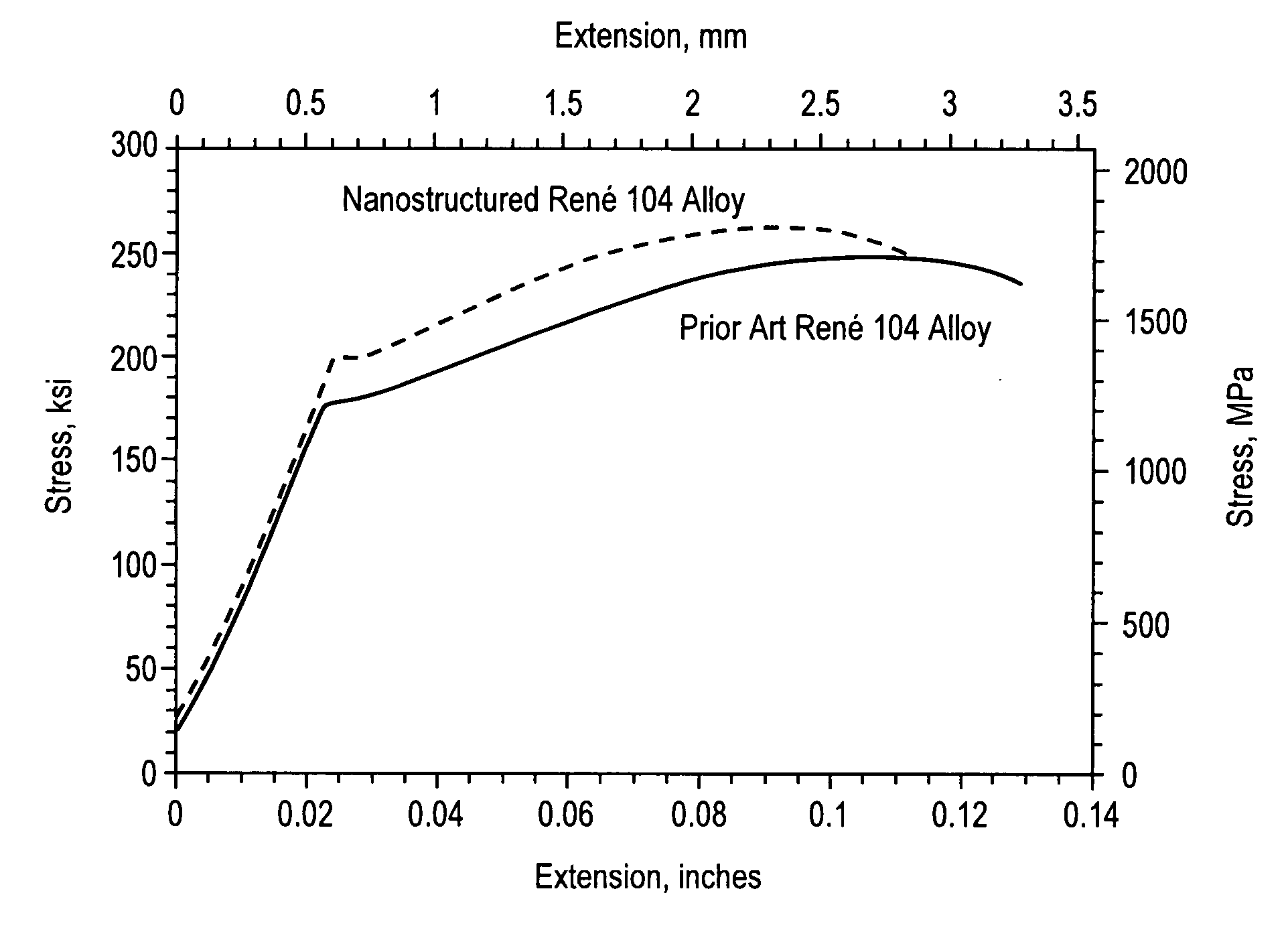
[0039] A René 104 alloy is a nickel-base superalloy having a nominal composition (in weight percent): 0.05 carbon, 3.4 aluminum, 0.05 zirconium, 3.7 titanium, 0.025 boron, 2.4 tantalum, 3.8 molybdenum, 0.9 niobium, 2.4 tantalum, 13 chromium, 20.6 cobalt, balance essentially nickel. The alloy was produced by consolidation of atomized powder, forging, and heat treatment. One sample of the powder was consolidated by hot isostatic pressing, extruded, and heat-treated to yield a micrometer-scale product. Another sample of the powder was cryomilled in liquid nitrogen and subsequently thermo-mechanically processed by hot isostatic pressing, extrusion, and heat treatment in a manner identical to the prior-art micrometer-scale product.

[0040] The two samples were examined by electron microscopy; and tensile tests were conducted. In the nanostructured René 104 alloy of the present disclosure, there is a distribution of small particles of zirconium and aluminum-rich oxides that also had been p...


PUM

PropertyMeasurementUnit
weight percentaaaaaaaaaa
temperaturesaaaaaaaaaa

Abstract

A superalloy-containing structural component includes a superalloy matrix, and a plurality of hard phase nanoparticles dispersed at grain boundaries within the superalloy matrix, wherein the plurality of hard phase nanoparticles dispersed at the grain boundaries comprise about 1 volume percent to about 30 volume percent of the structural component, and wherein the superalloy matrix and the plurality of hard phase nanoparticles dispersed at the grain boundaries within the base superalloy matrix have been thermo-mechanically processed to form the structural component. A method for making a structural component includes introducing dislocations into a superalloy particle matrix effective to form new grain boundaries within a plurality of superalloy particles, introducing hard phase dispersoid nanoparticles at a plurality of grain boundaries of the superalloy particles effective to pin the grain boundaries, and thermo-mechanically processing the superalloy particles and hard phase dispersoid nanoparticles to form the superalloy-containing structural component.

Description

BACKGROUND [0001] The present disclosure relates to superalloys, and more particularly to structural components comprising nanostructured superalloys. [0002] Superalloys are metallic alloys that can be used at high temperatures, often in excess of 0.7 of the absolute melting temperature. Many structural components, such as those used in aircraft engines or power generation devices, are formed from Fe-, Co-, or Ni-base superalloys. There is a constant drive towards improving the high temperature properties of these fatigue-limited structural components in order to increase the strength or life of the aircraft engine or power generation device. [0003] Nanostructured materials often exhibit superior mechanical properties (e.g., strength, hardness, ductility, and the like) relative to their larger-scale counterparts. Moreover, the fatigue initiation life of nanostructured materials is significantly higher than that of larger-grained materials since dislocation activity may be spread ove...

Claims


Application Information

Patent Timeline
Patent Type & Authority Applications(United States)
IPC IPC(8): C22C19/05C22F1/10
CPCB22F2003/248B22F2009/041B22F2998/10B22F2999/00C22F1/10C22C1/0433C22C19/056C22C32/00B82Y30/00B22F1/0003B22F9/04B22F3/02B22F3/15B22F3/20B22F3/24B22F2202/03B22F1/12
Inventor ORUGANTI, RAMKUMAR KASHYAPSUBRAMANIAN, PAZHAYANNUR RAMANATHANGIGLIOTTI, MICHAEL FRANCIS XAVIERIORIO, LUANA EMILIANAYOUNG, CRAIG DOUGLASSANYAL, SUCHISMITASRINIVASAN, DHEEPAAMANCHERLA, SUNDAR
Owner GENERAL ELECTRIC CO
Why Eureka
Try Eureka