Silver halide color photographic light-sensitive material and color image-forming method

a color photographic and silver halide technology, applied in the direction of photosensitive materials, photo-taking processes, instruments, etc., can solve the problems of reducing the total processing time required for high-chloride print materials to undergo all process steps, short-time printing service offered to customers, and reducing the total processing tim

Active Publication Date: 2007-07-05
FUJIFILM CORP
View PDF10 Cites 2 Cited by
  • Summary
  • Abstract
  • Description
  • Claims
  • Application Information

AI Technical Summary

Benefits of technology

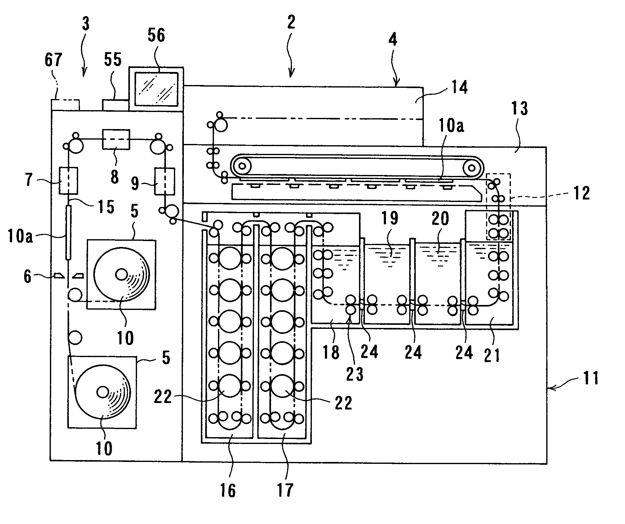
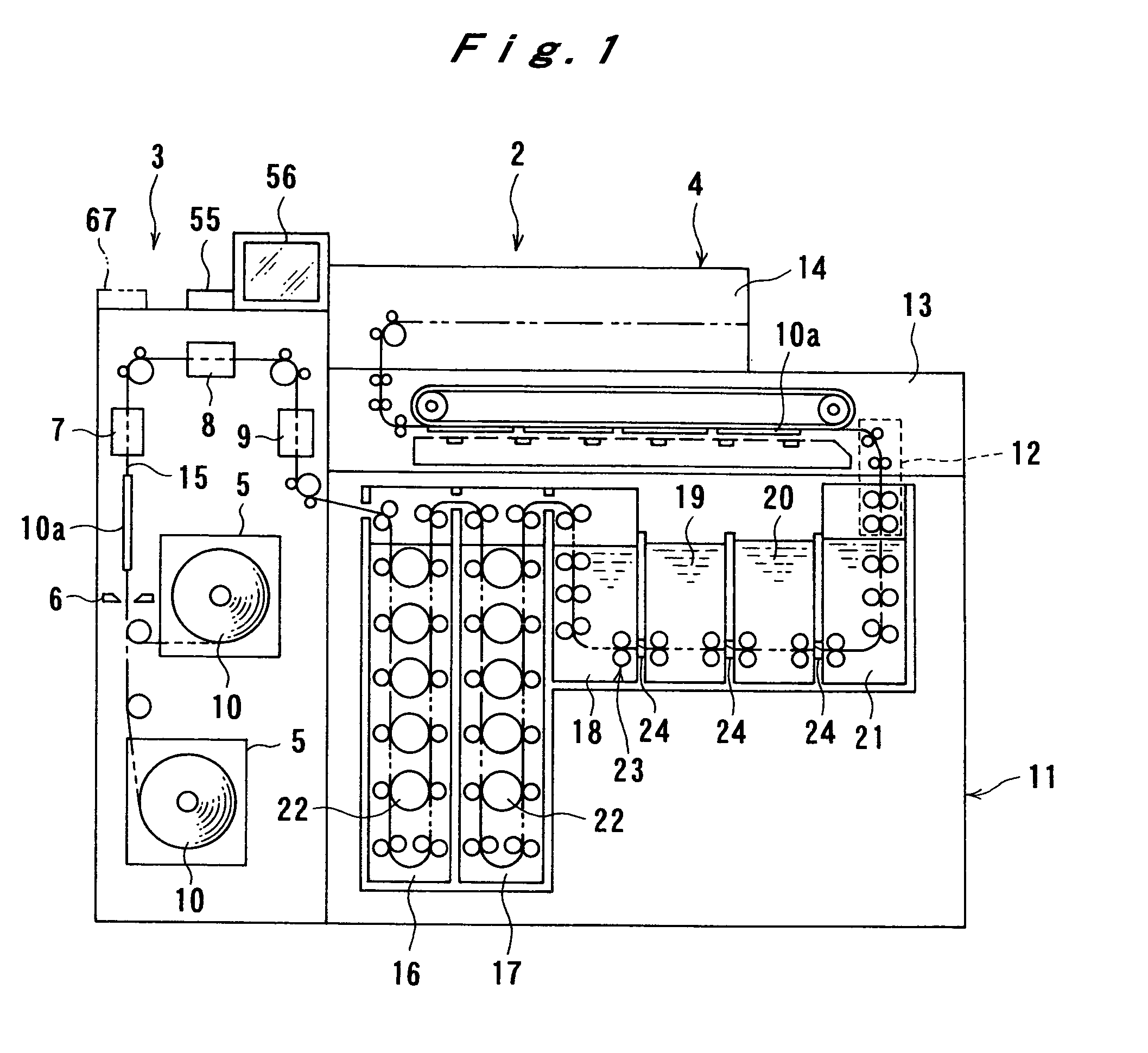
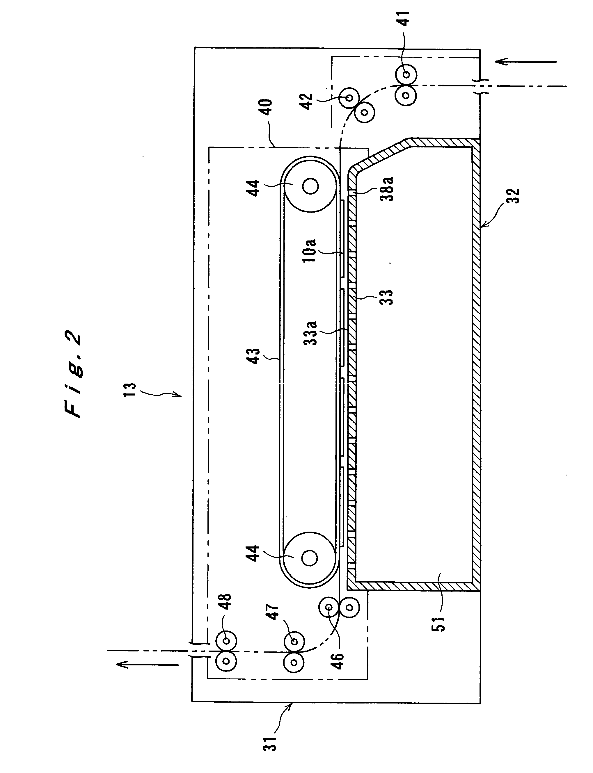
[0057] Other and further features and advantages of the invention will appear more fully from the following description, taken in connection with the accompanying drawings.

Problems solved by technology

However, it is still hard to say that the rapidity of such high-chloride print material-utilized rapid processing systems is sufficient as compared with the rapidity of image formation by other color image formation systems (e.g. an electrostatic transfer system, a thermal transfer system, an inkjet system), and therefore it is desired to further reduce the total processing time required for a high-chloride print material to undergo all process steps from the start of development to the end of drying.
Accordingly, reducing the print-processing time can directly lead to short-time print service offered for customers, so intensive studies have been conducted on silver halide photographic materials and processing systems that permit faster processing.
However, the dyes formed from those couplers have undesirable absorptions in the yellow-to-magenta region, and have a problem of worsening color reproduction.
Aiming to solve the problem, heterocyclic compounds having particular structures are proposed (e.g., in U.S. Pat. Nos. 4,728,598 and 4,873,183, and European Patent No. 0 249 453 A2), but those couplers each suffer a critical defect, such as low coupling activity or poor colorfastness of the dye formed.
These couplers are outstanding for hue and coupling activity, but the dye images formed from them do not always have sufficient fastness, and their lighffastness, in particular, is inferior to those formed from conventional couplers.
In addition, there arises the problem that, when the coupling activity of a coupler is raised by lowering pKa and rapid processing is carried out, a developing agent may be left in print owing to insufficient washing.
However, there is apprehension that speeding up conveying may cause an increase in the physical load on photosensitive materials under conveying, to result in sensitivity variation by abrasion in the wet state.
More specifically, when photosensitive materials come into contact with unforeseen extraneous substances or protuberances during conveying through processing solutions, and thereby some pressure is applied thereto, it is noted that there occurs a phenomenon in which the photosensitive materials undergo undesirable sensitization or desensitization; as a result, the prints obtained lose commercial value.
However, those arts are not always sufficient for wet abrasion sensitivity improvements when photographic materials are conveyed at increased speeds, namely in the case of high-speed conveying.
However, these methods have a drawback of exacerbating wet abrasion sensitivity.
This system requires the formation of frame information, to clearly indicate the sheet-by-sheet print boundaries, so it has the drawback that the areas bearing the frame information result in waste, and it has reduced productivity.
Preferably, the color print materials shipped from the factory are stored at low temperatures, but in fact, often they are left standing in places out of refrigeration; and worse, it often happens, depending on the district, that they are exposed to high temperature or high humidity situations.
As things stand now, however, they do not always meet quality requirements to a sufficient degree, specifically regarding the variations in developed color density and gradation, and the incidence of scratches.
Further, it turns out that increases in variation of color generation and incidence of scratches occur especially when the storage histories (temperature and humidity) of color print materials after manufacturing are improper.
However, none of those references suggest improvement of streak-form unevenness caused by high-density and high-speed exposure, and by reduction in the time period from exposure to color development.
However, this conveying method has the problem of suffering exposure unevenness, because vibrations are caused by various factors during the conveying and are transferred to an exposed area of photographic paper.
For instance, vibrations are transferred to, or load variations occur in, an exposed area of photographic paper by passage of the leading end or the trailing end of the photographic paper over a segment in which a level difference is present between a flatter guide supporting photographic paper in the exposure section and a conveying guide placed at the front of the exposure section, or by an action that the photographic paper takes to get over a conveying roller protruding from the flatter guide level, and thereby, exposure unevenness results.
In use of the aforementioned hard rollers providing exposure unevenness improvement in the sheet conveying method, however, it turned out that, in some cases, streaked unevenness came to develop in proximity to the points of passage over the hard rollers as the sub-scanning speed under exposure was increased.
Further, it has been found that the streaked unevenness developed conspicuously when photosensitive materials stored under circumstances of high temperature and low humidity underwent exposure.
As stated above, preferably photosensitive materials shipped from the factory are stored at low temperatures, but actually, often they are left standing in places out of refrigeration; and worse, it often happens, depending on the district, that they are exposed to high temperature or high humidity situations.

Method used


Image

  • Silver halide color photographic light-sensitive material and color image-forming method
  • Silver halide color photographic light-sensitive material and color image-forming method
  • Silver halide color photographic light-sensitive material and color image-forming method

Examples


example 1-1

(Preparation of Blue-sensitive Layer Emulsion BH-11)

[0648] Using a method of adding silver nitrate and sodium chloride simultaneously to a deionized distilled water containing a deionized gelatin to mix these, under stirring, cubic high silver chloride grains were prepared. In the course of this preparation, Cs2[OsCl5(NO)] was added, over the step of from 60% to 80% addition of the entire silver nitrate amount. Over the step of from 80% to 90% addition of the entire silver nitrate amount, potassium bromide (1.5 mol % per mol of the finished silver halide) and K4[Fe(CN)6] were added. Over the step of from 83% to 88% addition of the entire silver nitrate amount, K2[IrCl6] was added. Over the step of from 92% to 98% addition of the entire silver nitrate amount, K2[IrCl5(H2O)] and K[IrCl4(H2O)2] were added. At the completion of 94% addi of the entire silver nitrate amount, potassium iodide (0.27 mol % per mol of the finished silver halide) was added under vigorous stirring. The thus-o...

example 1-2

Processing B

[0675] Samples 1100 and 1105 in Example 1-1 each were made into a roll with a width of 127 mm; the resultant samples were exposed to light with a standard photographic image, using Minilab Printer Processor Frontier 340 (trade name, manufactured by Fuji Photo Film Co., Ltd.; wherein the sheet-conveying speed was set at 28 mm / sec); and then, the exposed samples were continuously processed (running test) in the following processing steps, respectively, until an accumulated replenisher amount of the color developing solution reached to be equal to twice the color developer tank volume.

[0676] The above samples were evaluated according to the same methods as adopted in Example 1-1, except that the photographic processing was performed under the following conditions.

ReplenisherProcessing stepTemperatureTimeamountColor development43.0° C.25.5 sec 45 mL / m2Bleach-fixing40.0° C.25.5 sec 35 mL / m2Rinse 140.0° C. 7.3 sec—Rinse 240.0° C. 3.5 sec—Rinse 340.0° C. 3.5 sec—Rinse 440....

example 1-3

[0684] Sample No. 1301 and Sample No. 1302 as described below were prepared. These Samples were processed according to the Processing A described in Example 1-1. As a result of making evaluations following Example 1-1, it is shown that these Samples were able to achieve the similar effects as the samples prepared in Example 1-1 according to the present invention.

—Preparation of Sample 1301—

[0685] A sample 1301 was prepared in the same manner as Sample 1105, except that the compositions of the third and fifth layers were changed as described below.

Third layer (Green-sensitive emulsion layer)Emulsion (a 1:3 mixture of GH-11 and GL-11 (mol ratio of silver))0.12Gelatin0.95Magenta coupler (Ma-48)0.21Oleyl alcohol0.33Color-image stabilizer (ST-1)0.04Color-image stabilizer (ST-2)0.28Fifth layer (Red-sensitive emulsion layer)Emulsion (a 4:6 mixture of RH-11 and RL-11 (mol ratio of silver))0.15Gelatin0.95Cyan coupler (IC-23)0.30Ultraviolet absorber (UV-5)0.36Dibutyl sebacate0.44Tris(2-eth...


PUM

PropertyMeasurementUnit
conveying speedaaaaaaaaaa
speedaaaaaaaaaa

Abstract

A color-image forming method in a silver halide color photographic light-sensitive material, having the steps of: performing exposure of the light-sensitive material cut into sheets; and subjecting the exposed light-sensitive material sheets to photographic processing, while conveying them with conveying rollers, with the sheet conveying speed being 40.0 to 100 mm/sec; wherein the light-sensitive material to be exposed contains any of: 1) a dye-forming coupler of formula (IA), 2) a compound of formula (I), and 3) 1.4 mg/m2 or more of a compound of formula (II);
wherein R′ and R″ are a substituent; Z is a hydrogen atom, or a coupling split-off group; A is an alkyl group, M is a cation, and R is an atom or group having 100 or lower total molecular weight.

Description

TECHNICAL FIELD [0001] The present invention relates to a silver halide color photographic light-sensitive material that is suitable for high-speed conveying processing, and to a color image-forming method using the same. More specifically, the invention relates to a color image-forming method by using a silver halide color photographic light-sensitive material and conveying the silver halide color photographic light-sensitive material in sheet form at a high speed in processes of photographic processing, which method can ensure color images formed with high quality and improvement in developer streaks, and further the invention relates to a silver halide color photographic light-sensitive material usable in the aforesaid method. BACKGROUND ART [0002] In recent years, high quality photographic light-sensitive materials suitable for rapid processing have been desired as a part of improvements in customer services for printing photographic information from digital cameras and as a mea...

Claims


Application Information

Patent Timeline
Patent Type & Authority Applications(United States)
IPC IPC(8): G03C1/46G03C1/09G03C1/16G03C1/30G03C5/04G03C7/30G03C7/32G03C7/34G03C7/38G03C7/392G03C7/407
CPCG03C1/09G03C1/16G03C7/407G03C7/3926G03C7/3825G03C7/346G03C7/3225G03C7/3022G03C5/04G03C1/30G03C2200/52G03C2200/60G03C2001/093G03C2001/096G03C2001/03517G03C2001/03535G03C2007/3025
Inventor DEGUCHI, YASUAKISOEJIMA, SHINOHSHIMA, NAOTOISHIZAKA, TATSUYATAKADA, KATSUYUKIYOSHIDA, FUTOSHIMARUHASHI, ATSUSHIMORIMOTO, YOSHINORIOHNO, TAKEHISA
Owner FUJIFILM CORP
Why Eureka
Try Eureka