
Superhard mold face for forming ele

a mold face and superhard technology, applied in glass tempering apparatus, manufacturing tools, food shaping, etc., can solve the problems of affecting the surface quality of the lens, reducing throughput times, and small aberrations or surface defects (e.g. unremovable parting agents) that can be very problematic, and achieve the effect of smoothing the optical elemen

Inactive Publication Date: 2007-07-12
SUNG CHIEN MIN
View PDF16 Cites 21 Cited by
  • Summary
  • Abstract
  • Description
  • Claims
  • Application Information

AI Technical Summary

Benefits of technology

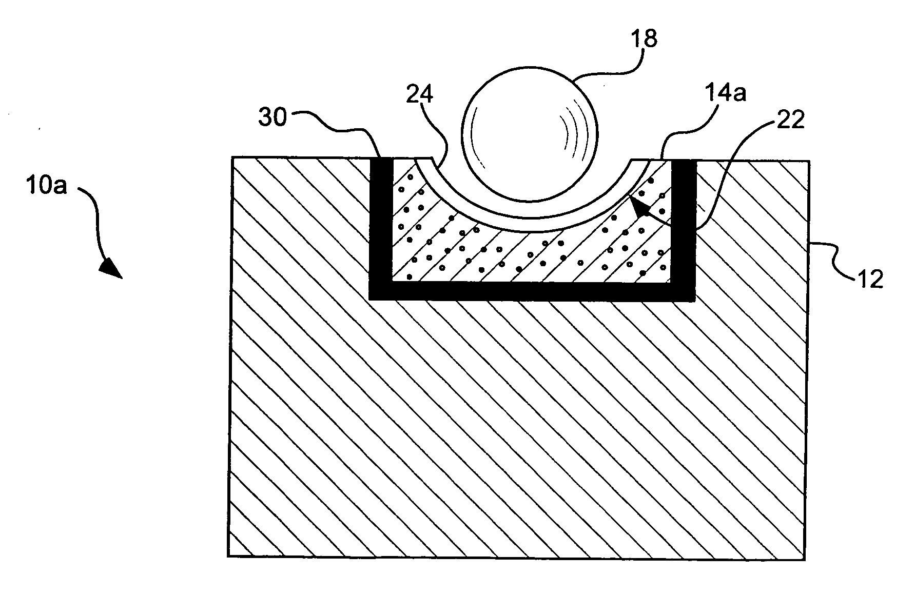
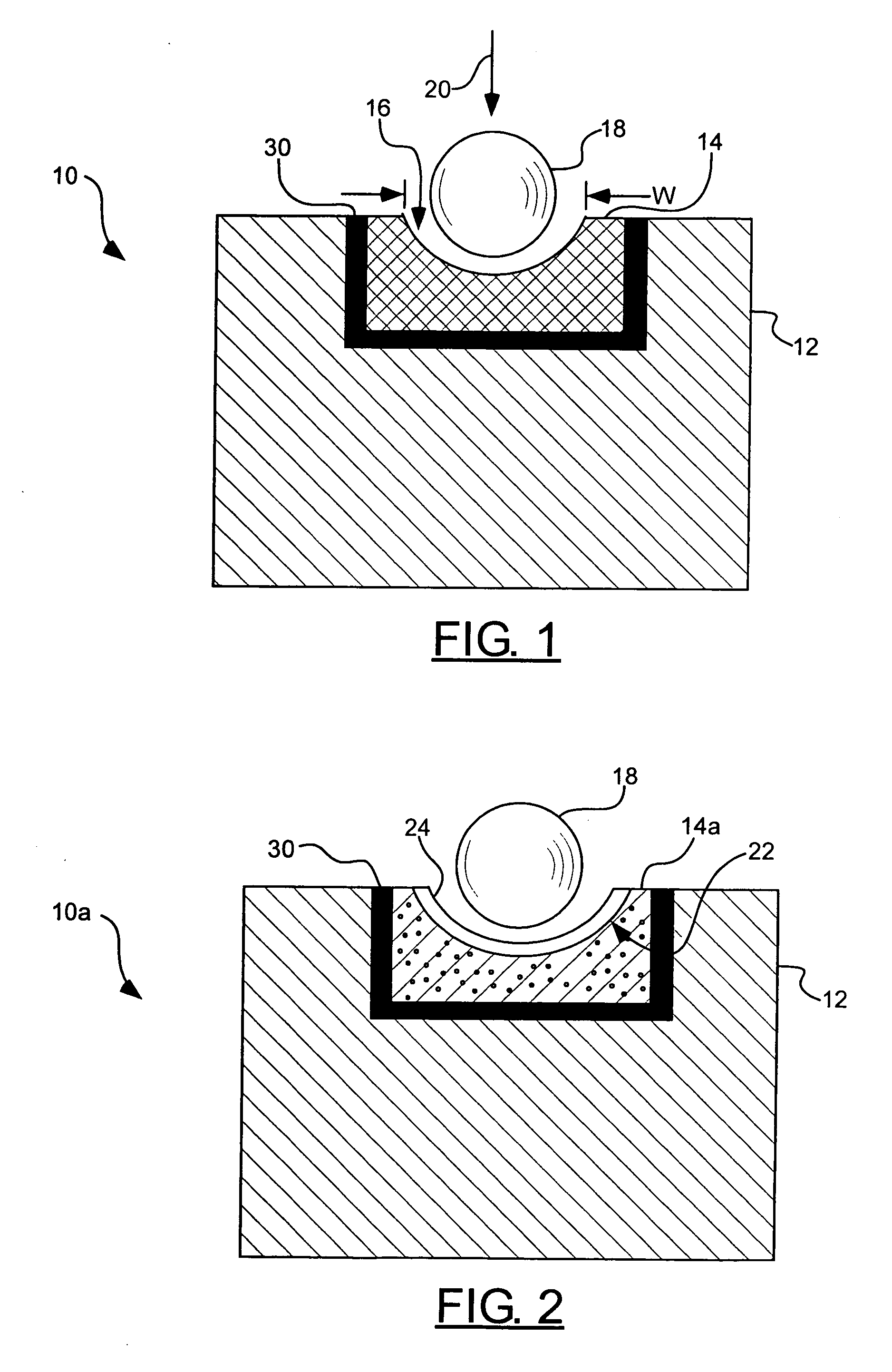
[0013] In accordance with another aspect of the invention, a mold assembly for forming optical elements is provided, including a support material and a molding material. The molding material can include a PCD compact coupled to the support material and can include a working surface defining a shape to be imparted to an optical element to be pressed in the mold assembly. In some cases, a superhard film can be applied over the working surface of the PCD molding material to improve the smoothness of the interface between the mold assembly and the optical element.
[0019] In accordance with a more detailed aspect of the invention, a flash of noble metal can be applied to the working surface of the molding material to further smooth the optical element as it is formed in the mold assembly.

Problems solved by technology

However, the addition of a parting agent may reduce throughput times and may also affect the surface quality of the lens.
As the small lens must divide light into millions of pixels, any small aberration or surface defect (e.g. unremoved parting agent) can be very problematic.
Moreover, shear stress resulting from deformation of the lens material when in an unheated state is not released during deformation of the lens material, resulting in distortion of the lens after the material has been pressed.
All these aberrations are generally unacceptable in forming high precision lenses.
However, the refractive index of polymers is generally low.
Polymer lenses are often also too soft to withstand scratches from dirt, dust, etc.
Most mold materials (e.g. tool steel, super alloys) cannot withstand extended use in such extreme temperature ranges.
Even when so configured, however, the mold can last for only a few hundreds “runs” (the life of a typical steel mold is only on the order of ten runs).
Thus, current optical lens mold makers have been faced with the problem of increasing the hardness and surface smoothness of molds in order to meet the ever increasing demands for optical integrity, while also utilizing improved optical materials that demand very high operating temperatures.
However, DLC often cannot withstand temperatures higher than about 400° C. in repeated cycling.
In addition, DLC is generally very thin (e.g. <1 micron), so its overall wear resistance is limited.
Also, DLC is notoriously difficult to adhere to the substrates used in press molding optical lenses.
During the thermal cycling of the molding process, the thermal mismatch between low expansion DLC and a high expansion substrate can cause stress fatigue resulting in “flaking” of the DLC coating.
Due to these dangling electrons, reaction may result causing pitting of either the molding material or the DLC.
However, the improved optical qualities have generally come at the cost of raising the melting point of the glass used as a lens material.

Method used


Image

  • Superhard mold face for forming ele
  • Superhard mold face for forming ele

Examples


example 1

[0083] Micron (about 2-6 micron) diamonds are mixed with tungsten powder and subject to about 6 GPa pressure and about 1500° C. temperature for about 20 minutes. The PCD produced has a cylindrical form with a diameter of about 30 mm and a height of about 20 mm. Due to the presence of W, the PCD is electro-discharge formed to create a depression therein. Subsequently, the depression is ground with diamond tools and lapped / polished with diamond powder of decreasing size to achieve a mirror finish. The mold so formed can be used directly or it can be further coated with diamond film or cermet composite.

example 2

[0084] A sintered cylinder is used as the mold material. It is formed with a cavity and smooth finish. The surface is coated with cermet composite coating that grades the composition from SiC to Tantalum so the surface has little or no grain boundary.


PUM

PropertyMeasurementUnit
Temperatureaaaaaaaaaa
Pressureaaaaaaaaaa
Temperatureaaaaaaaaaa

Abstract

Mold assemblies for forming optical elements including a support material and a molding material are disclosed and described. In one aspect, the molding material can include a single crystal diamond coupled to the support material and includes a working surface defining a shape to be imparted to an optical element to be pressed in the mold assembly. In another aspect, the molding material can include a PCD compact coupled to the support material and includes a working surface defining a shape to be imparted to an optical element to be pressed in the mold assembly. In yet a further aspect, the molding material may include a cermet composite coating material which provides a gradient of one material coupled to the support material to another material at a working surface of the molding material which defines a shape to be imparted to an optical element to be molded.

Description

FIELD OF THE INVENTION [0001] The present invention relates to mold assemblies having superhard working surfaces for use in forming optical elements and other at least partially spherical elements. Accordingly, the present invention involves the fields of chemistry, physics, and materials science. BACKGROUND OF THE INVENTION [0002] Press molds are widely used in the manufacture of various parts which are desired to be produced with relatively high throughput. For example, injection molding of polymer materials for sealing semiconductor devices (e.g. diodes) is a routine production practice. Ophthalmic lenses are also molded in a similar fashion. In recent years, relatively small camera lenses, such as those used in cell phones and similar devices, have been produced in large quantities. Such lenses may be made of transparent polymers or optical glasses. In a typical application, raw material in the form of a bead is pressed and flattened between two anvils in order to form a lens fr...

Claims


Application Information

Patent Timeline
IPC IPC(8): C03B23/00A23G1/22C03B11/08C03B7/14
CPCC03B11/084C03B11/086C03B2215/24C03B2215/11C03B2215/12C03B2215/07
Inventor SUNG, CHIEN-MIN
Owner SUNG CHIEN MIN
Learn More