Method for manufacturing grin lens and grin lens

a technology of grin lens and grin lens, which is applied in the direction of manufacturing tools, instruments, lenses, etc., can solve the problems that the small diameter grin lenticular optical fiber cannot be stably produced, and achieve the effects of small diameter, efficient and easy manufacturing, and large numerical apertur

Active Publication Date: 2007-07-12
TOYO SEIKAN GRP HLDG LTD
View PDF4 Cites 11 Cited by
  • Summary
  • Abstract
  • Description
  • Claims
  • Application Information

AI Technical Summary

Benefits of technology

[0024] According to the present invention, a GRIN lens having a large numerical aperture and a small diameter can efficiently and easily be manufactured. The GRIN lens of the present invention can provide, for example, a small diameter of 1 mm or smaller, and thus an optical device such as an optical fiber collimater or the like can be miniaturized. Further, when the GRIN lens is deposited on the tip end of an optical fiber, the axis of the GRIN lens and the optical fiber is automatically consistent with each other due to a self-alignment effect caused by the surface tension of molten glass, thus manufacture becomes significantly easy.

Problems solved by technology

However, when the GRIN lens base material is re-heated at high temperatures of 1,800 to 2,000° C., the base material normally foams and can not be stretched, and thus the small diameter GRIN lenticular optical fiber was unable to be stably produced.

Method used


Image

  • Method for manufacturing grin lens and grin lens
  • Method for manufacturing grin lens and grin lens
  • Method for manufacturing grin lens and grin lens

Examples


example 1

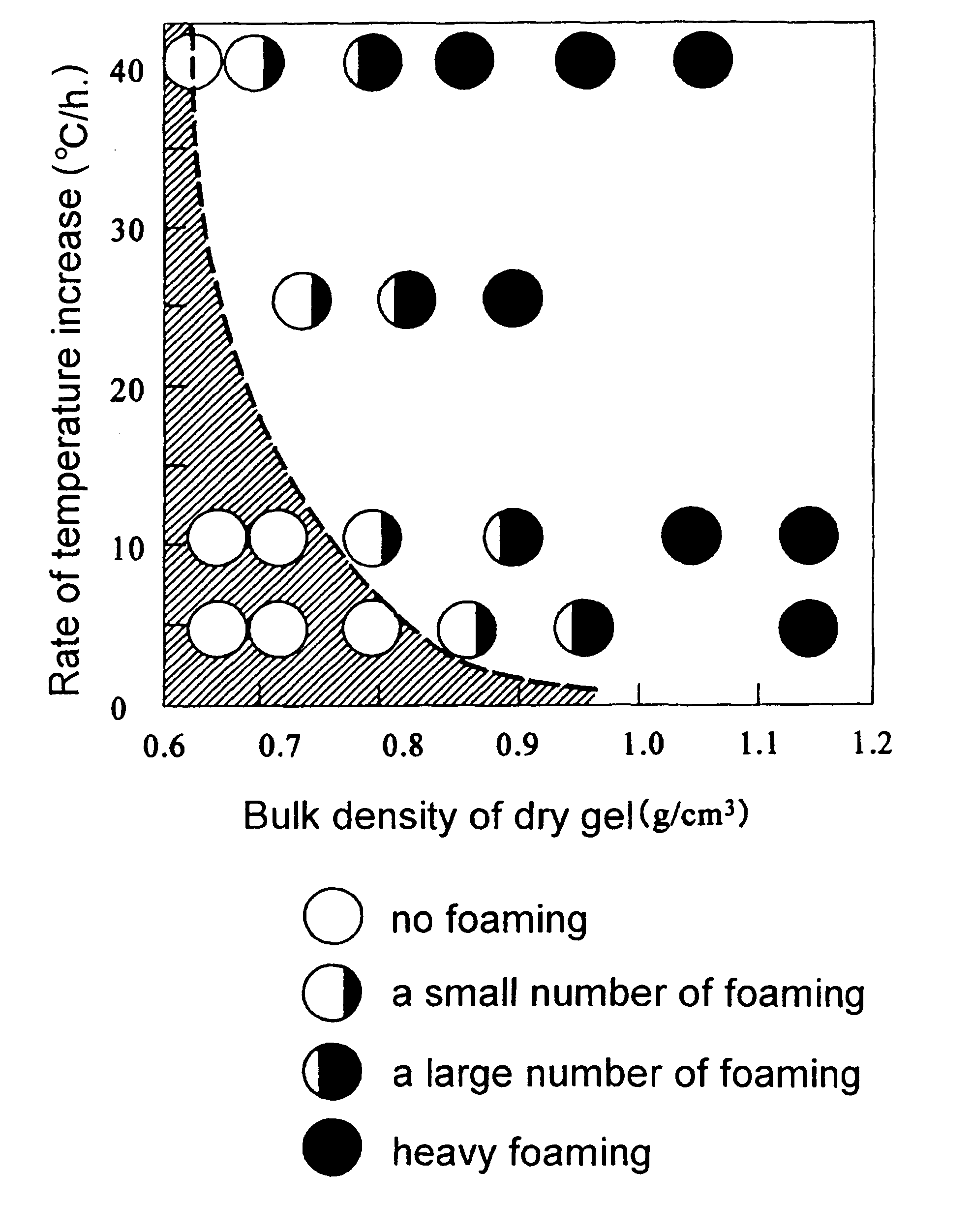
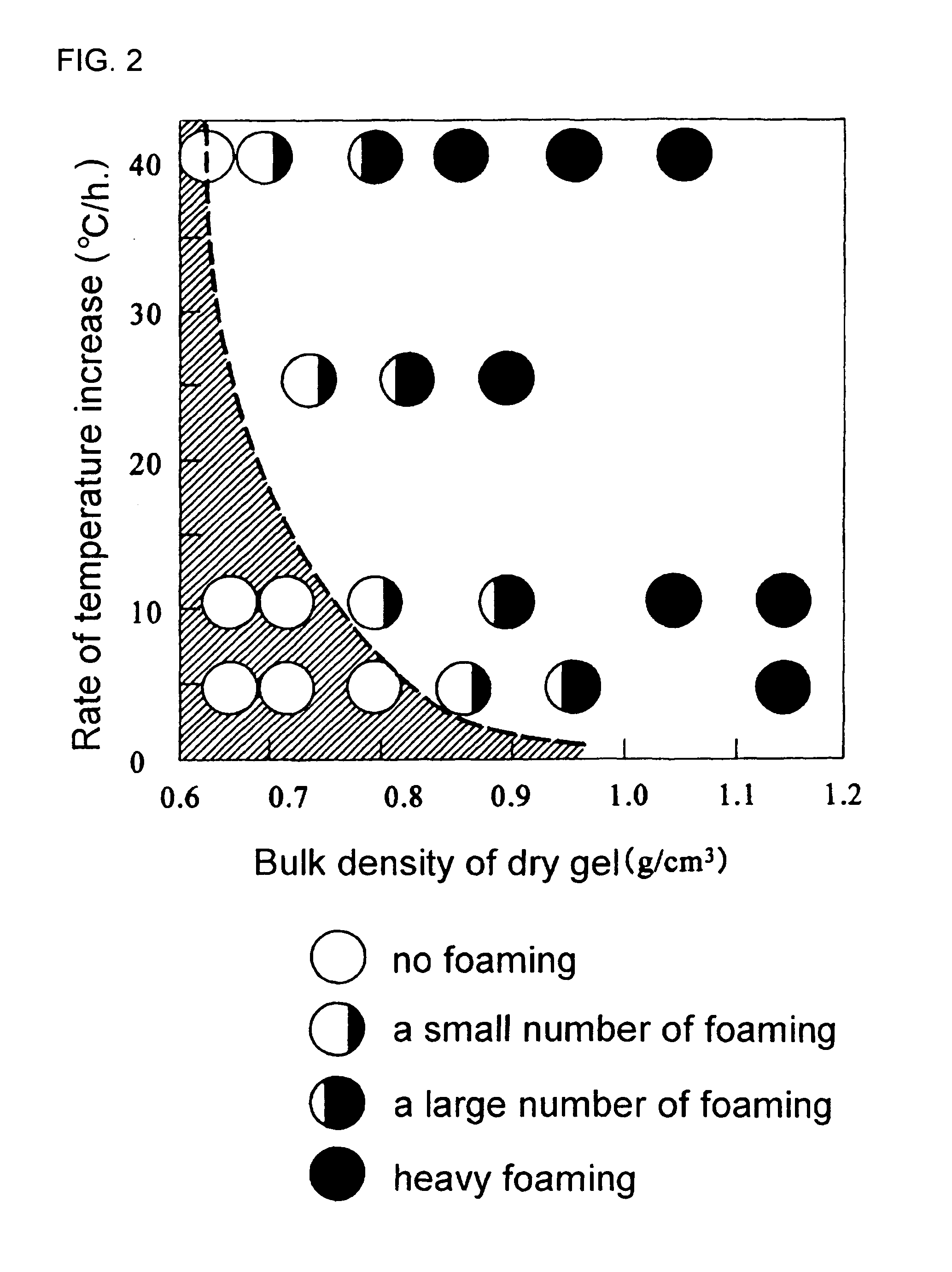
[0032] 64.7 g of tetramethoxysilane (TMOS) was combined with 39.16 g of ethanol, 18.27 g of dimethylformamide (DMF) and further 7.76 g of 0.056 N hydrochloric acid, and mixed. Thereafter, 25.53 g of titanium tetrabutoxide was combined with 39.74 g of ethanol and 18.27 g of DMF was dripped and mixed while agitating. The solution was dripped with 28.37 g of distilled water (water) and 24.76 g of ethanol, and mixed to make a sol liquid. This sol liquid was poured in a test tube having an inner diameter of 14 mm, sealed with aluminum foil, then placed in a thermostatic chamber at 60° C. for 5 days, and aged. Gel completing the aging process was immersed in 1.5 N hydrochloric acid for 3 hours to form a concentration distribution on a Ti component, then immersed in water for 24 hours and washed. The washed wet gel was repeatedly immersed in 1.5 N hydrochloric acid for 6 hours to form the concentration distribution on the Ti component, then immersed in ethanol for 24 hours and washed. The ...

example 2

[0037] 64.7 g of tetramethoxysilane (TMOS) was added with 39.16 g of ethanol, 18.27 g of dimethylformamide (DMF) and further 7.76 g of 0.056 N hydrochloric acid, and mixed, thereafter, 41.0 g of tantalum ethoxide added with 39.74 g of ethanol and 18.27 of DMF was dripped and mixed while agitating. The solution was dripped with 28.37 g of distilled water (water) and 24.76 g of ethanol, and mixed to make a sol liquid. This sol liquid was poured in a test tube having an inner diameter of 14 mm, sealed with aluminum foil, then placed in a thermostatic chamber at 60° C. for 5 days, and aged. The gel completing the aging process was immersed in a 0.1% hydrofluoric acid aqueous solution for 6 hours to form a concentration distribution on a Ti component, then immersed in water for 24 hours and washed, and further immersed in ethanol for 24 hours and washed. The gel completing the washing process was removed, placed in the thermostatic chamber at 60° C. for 5 days and in the thermostatic cha...


PUM

PropertyMeasurementUnit
partial pressuresaaaaaaaaaa
temperatureaaaaaaaaaa
diameteraaaaaaaaaa

Abstract

A method for manufacturing a GRIN lens includes the steps of forming a wet gel provided with a concentration distribution having a different concentration of a refractive index distribution imparting metal that differs in concentration in a radial direction, drying the wet gel to form a dry gel having a bulk specific gravity ρ (g/cm3), sintering the dry gel to form a GRIN lens base material and stretching the GRIN lens base material while heating. The method is characterized in that, in the step of sintering the dry gel, partial pressures of oxygen during sintering at 800° C. or higher are 10−1 Pa or lower and also the relation between a rate of temperature increase ν (° C./hr) and a bulk density ρ of the dry gel during sintering at 1,000 to 1,150° C. is defined by ν≦105*EXP (−12ρ). As a result of this, the GRIN lens, which has a large numerical aperture and a small diameter, can stably and easily be manufactured.

Description

BACKGROUND OF THE INVENTION [0001] 1. Technical Field [0002] The present invention relates to a graded index optical device which can particularly be applied to an optical device such as an optically coupled component for optical communication, a camera, an endoscope or the like, and a method for manufacturing the graded index optical device by a sol-gel process. [0003] 2. Description of Related Art [0004] A graded index optical device has received attention, for example, as a lens having a small spherical aberration used when radiant light from a semiconductor laser is made highly efficiently incident on an optical fiber, and also, as a lens for image transmission of a camera or the like since an edge face of the lens is smooth and an optional focal length can be provided by changing the length of a circular cylinder. In particular, the shape is compact and cylindrical, thus it has been employed as a lens that is easily aligned with an axis of an optical system, easily retained and...

Claims


Application Information

Patent Timeline
Patent Type & Authority Applications(United States)
IPC IPC(8): C03B8/00B32B17/06B32B9/00
CPCC03B19/12C03B23/047G02B3/0087C03B2201/42C03B2203/26C03B2201/40
Inventor MATSUMURA, HIROYOSHISUZUKI, TAROACHIWA, TORU
Owner TOYO SEIKAN GRP HLDG LTD
Why Eureka
Try Eureka