Manufacturing Method and Apparatus of Phase Shift Mask Blank

a manufacturing method and mask technology, applied in the field of manufacturing methods and apparatus of phase shift mask blanks, can solve the problems of poor yield, complicated constitution of phase shift masks, and high degree of manufacturing techniques, and achieve satisfactory yield

Active Publication Date: 2007-08-16
HOYA CORP
View PDF22 Cites 9 Cited by
  • Summary
  • Abstract
  • Description
  • Claims
  • Application Information

AI Technical Summary

Benefits of technology

[0014] The present invention has been developed under the aforementioned background, and a first object thereof is to provide a manufacturing method of a phase shift mask blank in which dispersions of a phase angle and transmittance among blanks can be reduced as much as possible and a yield is satisfactory.

Problems solved by technology

These phase shift masks have a complicated constitution and requires a high degree of manufacturing technique as compared with the conventional photo mask which has only the light strength information.
However, with shortening of the wavelength of laser for use in exposure to ArF excimer laser (193 nm) from i-ray (365 nm) and KrF excimer laser (248 nm), the following problem is generated in the conventional halftone phase shift mask and the manufacturing method of the mask.
That is, in mass production of the phase shift mask blanks, when there are dispersions of the phase angle and transmittance among the blanks or in the plane, yield is bad.
Particularly in the mask blanks for the short wavelength of ArF or F2 excimer laser, the dispersions of the phase angle and transmittance among the blanks and in the plane in the conventional mask blanks for i-ray and KrF excimer laser are large, and the yield is bad.
Therefore, the mask blanks cannot be applied as they are.

Method used


Image

  • Manufacturing Method and Apparatus of Phase Shift Mask Blank
  • Manufacturing Method and Apparatus of Phase Shift Mask Blank
  • Manufacturing Method and Apparatus of Phase Shift Mask Blank

Examples


Embodiment Construction

[0092] Examples of the present invention will be described hereinafter in further detail.

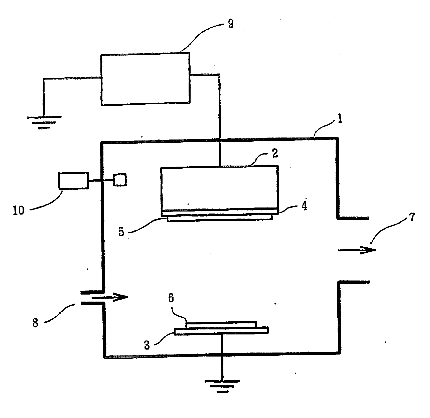
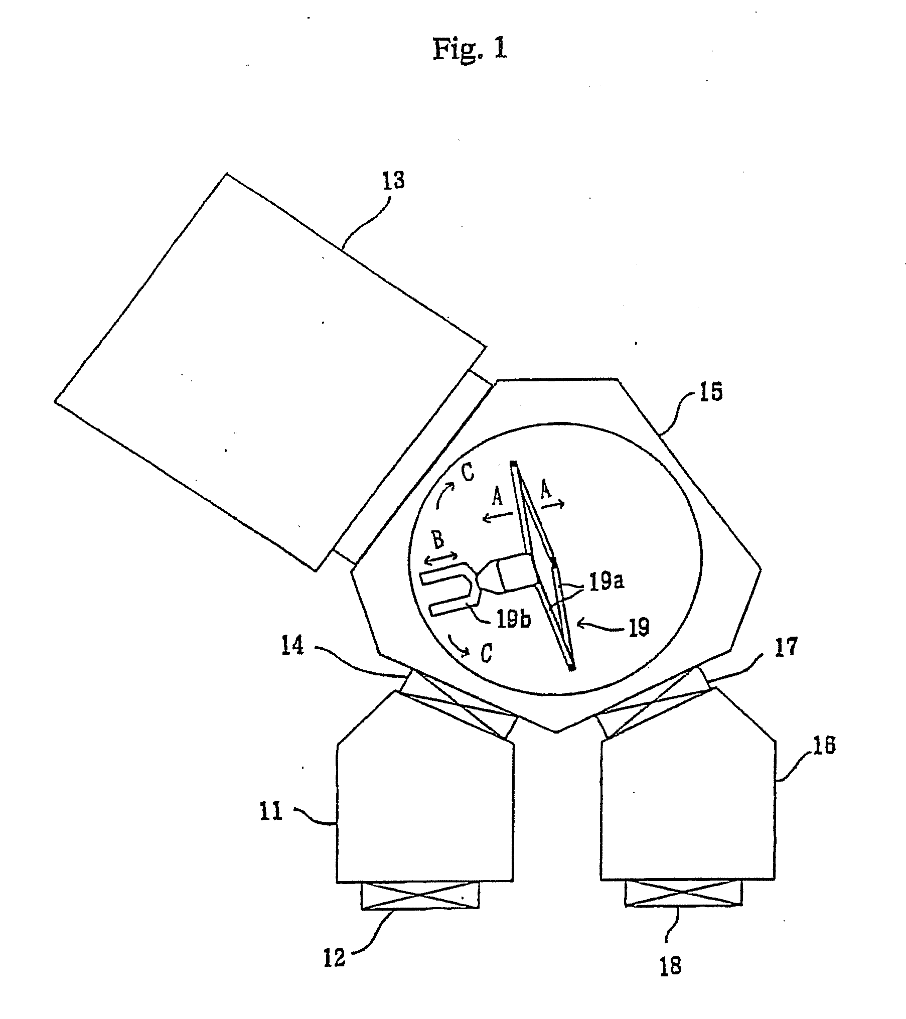
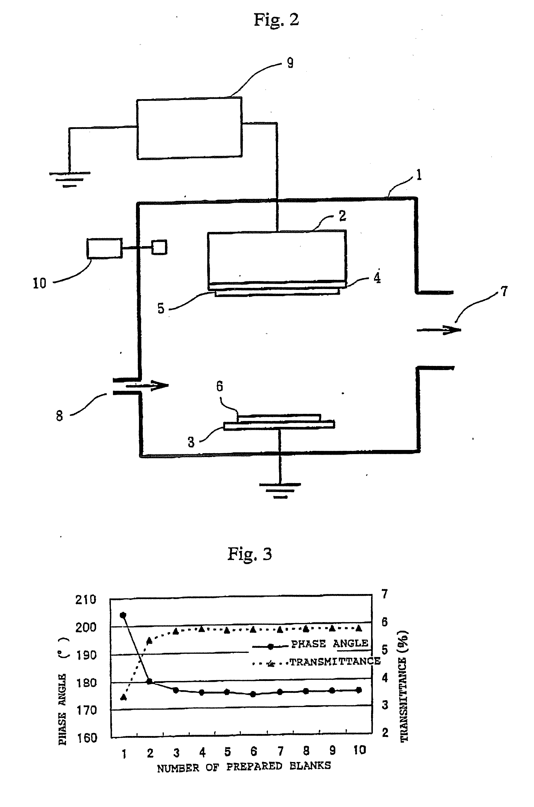
[0093] A DC magnetron sputtering apparatus described above with reference to FIG. 1 was used to continuously form films of 200 halftone phase shift mask blanks for ArF excimer laser (193 nm) one by one at constant intervals.

[0094] Concretely, a mixed target (Mo:Si=8:92 mol %) of molybdenum (Mo) and silicon (Si) was used to form a nitrided thin film (film thickness of about 670 angstroms) of molybdenum and silicon (MoSiN) on a transparent substrate by reactive sputtering (DC sputtering) in a mixed gas atmosphere (Ar:N2=10%:90%, pressure: 0.1 Pa) of argon (Ar) and nitrogen (N2). In this manner, the phase shift mask blank (film composition: Mo:Si:N=7:45:48) for ArF excimer laser (wavelength of 193 nm) was obtained.

[0095] Here, a sputtering chamber 13 in the DC magnetron sputtering apparatus shown in FIG. 1 has a vacuum tank 1 as shown in FIG. 2. A magnetron cathode 2 and substrate holder 3 are d...


PUM

PropertyMeasurementUnit
angleaaaaaaaaaa
phase angleaaaaaaaaaa
transmittanceaaaaaaaaaa

Abstract

There is disclosed a manufacturing method of a phase shift mask blank in which dispersions of phase angle and transmittance among blanks can be reduced as much as possible and yield is satisfactory. In the manufacturing method of the phase shift mask blank, a process of using a sputtering method to continuously form a thin film on a transparent substrate comprises: successively subjecting a plurality of substrates to a series of process of supplying the transparent substrate into a sputtering chamber, forming the thin film for forming a pattern in the sputtering chamber, and discharging the transparent substrate with the film formed thereon from the sputtering chamber; supplying and discharging the transparent substrate substantially at a constant interval; and setting a film formation time to be constant among a plurality of blanks.

Description

BACKGROUND OF THE INVENTION [0001] i) Field of the Invention [0002] The present invention relates to a manufacturing method and apparatus of a phase shift mask blank which is suitable particularly for ArF or F2 excimer laser. [0003] ii) Description of the Related Art [0004] In recent years, it has been clarified that high resolution and focus depth are two important properties required for photolithography but are in a contradictory relation with each other, and that a practical resolution cannot be enhanced only by high NA and short wavelength of a lens of an exposure apparatus (Monthly Semiconductor World 1990.12, Applied Physics Vol. 60, November, 1991, and the like). [0005] Under such situation, phase shift lithography has been noted as the next-generation photolithography technique, and partially brought to practical use. The phase shift lithography is a method for enhancing the resolution of photolithography by change only of a mask without changing an optical system. When a p...

Claims


Application Information

Patent Timeline
Patent Type & Authority Applications(United States)
IPC IPC(8): C23C14/00C23C14/06C23C14/22C23C14/34G03F1/00G03F1/26G03F1/32G03F1/68H01L21/027
CPCC23C14/0036C23C14/0641C23C14/225G03F1/68G03F1/08G03F1/26G03F1/32C23C14/505
Inventor NOZAWA, OSAMUMITSUI, HIDEAKI
Owner HOYA CORP
Why Eureka
Try Eureka