
Variable-tooth gear with sliding-sheet deforming teeth

a technology of sliding sheet and teeth, applied in the direction of gearing, mechanical equipment, basic electric elements, etc., can solve the problems of complex design and process, high manufacturing cost, and inability to achieve output, etc., and achieve high transmission efficiency, simple structure, and large load capacity

Inactive Publication Date: 2007-08-30
BEIJING VIT MOBILE TECH
View PDF67 Cites 30 Cited by
  • Summary
  • Abstract
  • Description
  • Claims
  • Application Information

AI Technical Summary

Benefits of technology

[0004] With regard to this, the main object of the invention is to provide a variable-tooth gear with sliding-sheet deforming teeth, which has characteristics of large load capacity, high transmission efficiency, simple structure, low cost and compactness. This variable-tooth gear realizes, to the core, the concept of “continuously variable transmission via gear meshing”, and can be widely applied to vehicles or industrial fields of high speed and large power.
[0005] A further object of the invention is to provide a variable-tooth rack with sliding-sheet deforming teeth, which has characteristics of large load capacity, high transmission efficiency, simple structure, low cost and compactness. This variable-tooth rack realizes in deed the concept of “continuously variable transmission via rack meshing”, and can be widely applied to vehicles or industrial fields of high speed and large power.
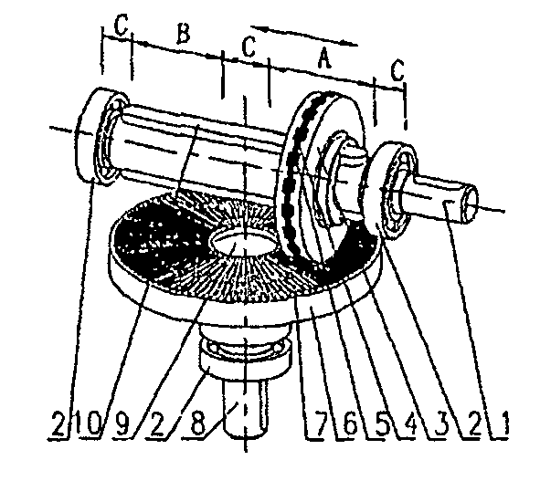
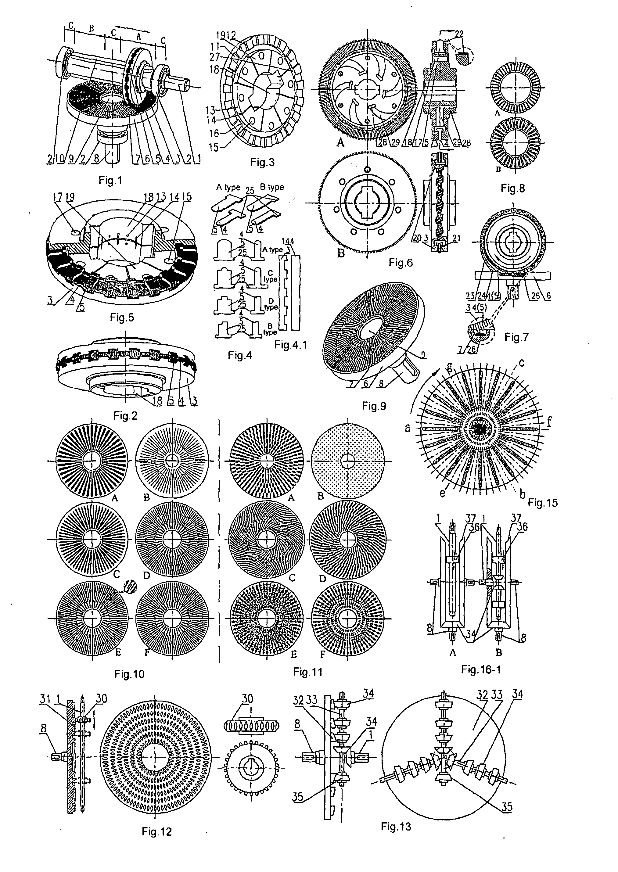
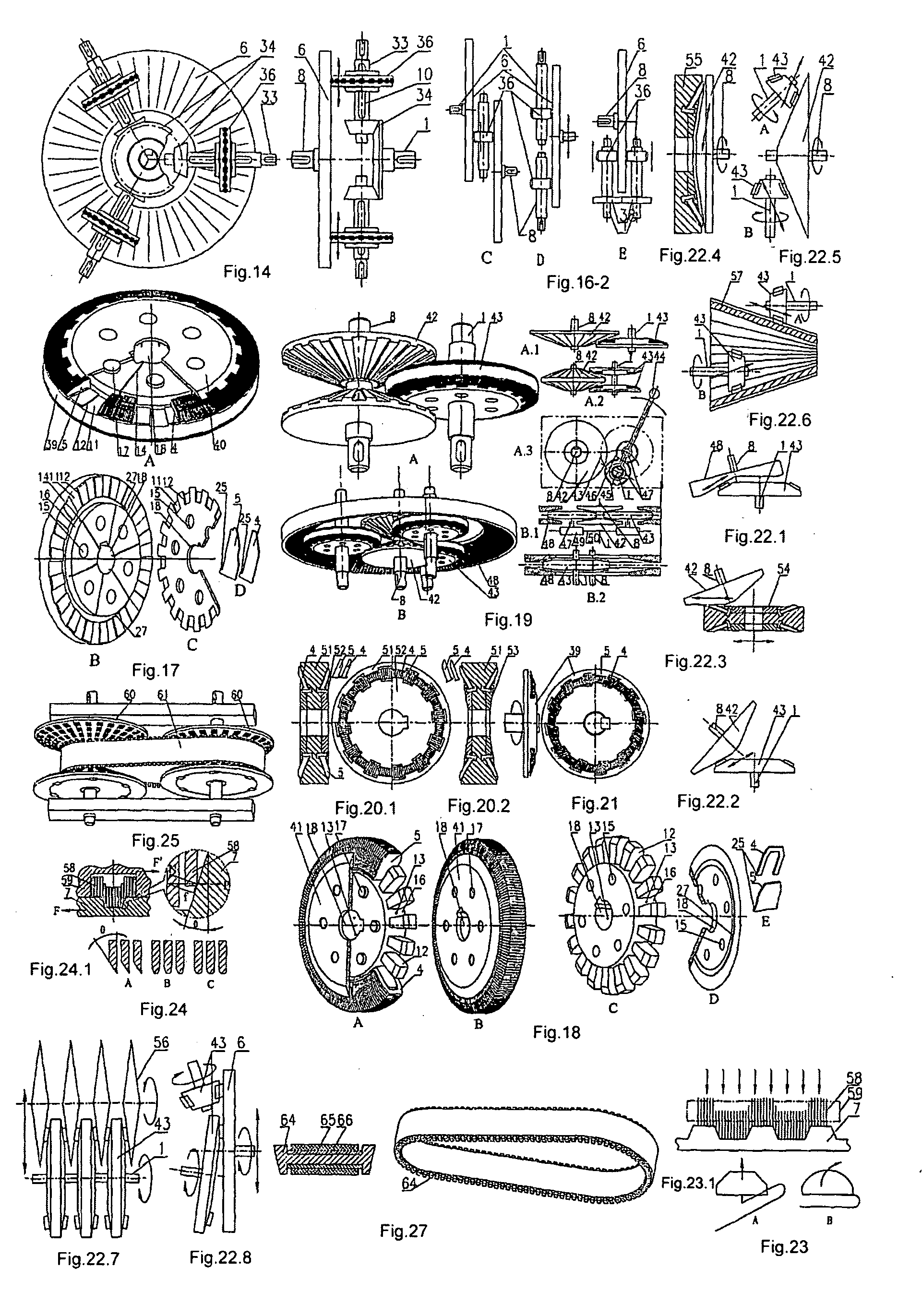
[0023] a CVT with a variable-tooth cylindrical gear: the input shaft is coupled to the tooth-and-groove wheel, the variable-tooth gear is coupled to an output shaft via guiding splines or splines, the variable-tooth gear can freely move in the axial direction while transmitting torques, thereby continuously varying the meshing radius with the tooth-and-groove wheel to perform continuously variable transmission; an electromagnet or a permanent magnet can be provided on the tooth-and-groove wheel disc or at a place corresponding thereto so as to induce magnetic forces onto the sliding-sheets to make them return, or a permanent magnet or an electromagnet can be provided inside the variable-tooth gear, all sliding-sheets are permanently magnetized or electro-magnetized so as to be moved outwards via repellent forces to implement returning; alternatively, returning can be performed via the magnetic induction interactions between the magnetic field and the inducing current induced by the movement of sliding-sheets in the magnetic field (or alternate electromagnet field); alternatively, the generation device which generates the returning driving forces for sliding-sheets can be stationary and does not participate in motion, the electromagnet itself can be stationary and does not follow the tooth-and-groove disc to move, the sliding-sheets can be attracted to return by magnetic induction; (as for returning via electromagnetic forces) the design radial dimension of free centrifugal returning at the state of sliding-sheets separating from the gear wheel can be larger than, equal to, or smaller than the returning radial dimension when meshing with the tooth-and-groove wheel; a central recess 9 can be provided at the center of the tooth-and-groove wheel; the distance between the grooves of the tooth-and-groove wheel can be or can not be a multiple of the distance between the sliding-sheet groups; a lubricant hole (or a lubricant slit) can be provided on the wheel body, the inside of the wheel body can also be designed as a structure of a centrifugal pump, a friction traction ring 22 can be provided at the outer edge of the variable-tooth gear, the friction traction ring can be made of elastic materials such as rubber; an non-closed outer constraining ring for sliding-sheets 23 can be disposed on the outer circumference of the variable-tooth gear, an arc-shaped transition guiding zone 24 can be designed in the direction that faces the sliding-sheets' rotations into the constraining ring so as to improve the operation reliability, now the sliding-sheets can be dispensed with the stop legs, the sliding-sheets can also be replaced by sliding-needles; alternatively, a stress-suppressing pad layer 26 can be attached to the bottom of the concave grooves of the tooth-and-groove disc, which pad is generally made of elastic and soft filling materials, such as spray coating rubber materials, etc.;
[0046] the rollers of the rotary shaft roller wheel can take a conic shape, and the performance of continuously variable transmission is basically improved by using of the self-locking property; its working surface can also be made to be an arc shape; alternatively: the rotary shaft roller wheel can be replaced with a gear, a bevel gear, a worm wheel or a worm to mesh with the sliding-sheets of the variable-tooth cylindrical gear, the variable-tooth cylindrical gear can also be replaced with a variable-tooth conic gear; alternatively: a transmission in which the rotation shaft of the rotary shaft roller wheel is fixed and the rotation shaft of the variable-tooth cylindrical gear can rotate is employed;
[0067] an infinitely meshing transmission with sliding-blocks: its infinitely meshing device unit is a “sliding-block infinitely meshing” device, the tooth profiles on the inner side of the sliding meshing triangular toothed belt, a chain 186 whose triangular teeth at the inner side meshes through sliding, capable of meshing via sliding with the tapered tooth blocks 187 by automatically finding the meshing points through mechanical sliding, the tapered tooth blocks 187 moves in the trails 189, in x direction, they can return via centrifugal forces; in y direction, they are self-locked, in operation, the tapered tooth blocks can freely return in x direction until they reach the optimal meshing end of the triangular-tooth driving belt capable of meshing via sliding 186 so as to mesh sufficiently with the surfaces of the triangular teeth; they are self-locked in y direction, by juxtaposing and operating two types of tapered tooth blocks, denoted by a and b, which are orientated along complementary rails, it is realized thus that the infinitely meshing device unit can infinitely mesh with the triangular-tooth driving belt capable of meshing via sliding 186 at any point in the regions that the tooth blocks can slide;
[0101] the pressing belt includes: a metal belt of the meshing type, a metal belt with meshing convex teeth and concave grooves configured by alternately combining metal rings and wide, narrow metal blocks; or: a metal belt configured by firstly composing a wide metal block group from wide metal blocks and a narrow metal block group from narrow metal blocks and then alternately combining the wide metal block group with the narrow metal block group; or: the narrow metal blocks can employ “a cross section of an arc shape”, the regions of both sides of the wide metal blocks that participate in meshing can be provided with slant surfaces, whereby the continuously variable transmission performance is basically improved by means of the self-locking meshing property; alternatively: the wide, narrow metal blocks can be replaced with “concave metal blocks” and “convex metal blocks” of the flexible metal belt for the transmission with variable-tooth conic gear of a small taper.

Problems solved by technology

These transmissions have the following disadvantages in general, (1) it is hardly possible to achieve an output of ultra low rotary speed, and the range of speed shifting is relatively narrow; (2) the transmission torque is small and the transmission power is not quite large; (3) low load capacity, and low resistance to overload and impact; (4) high requirements on the manufacture and lubrication of the components, with the components being of short life endurance, with complex designs and processes and high manufacture costs; (5) high sliding ratio and low mechanical efficiency; with some of them being even present with the phenomena of discontinuous pulse outputs and power flows.
As far as the prior art is concerned, all CVTs of the friction type need large normal pressing forces to transmit power, thereby increasing the loads to each bearing; there exists significant elastic sliding and geometrical sliding among transmission bodies; efficient contact surfaces for power transmitting, theoretically being line contact or point contact, are small, so as to cause large local stresses, and even to cause the working surfaces to be abraded or be stuck in serious cases; the transmission efficiency is low and the transmitting power is limited; and their service life are short.
This approach is different from both the meshing transmission and friction transmission, however it is an intervenient quasi-meshing transmission manner.
However, the chain of this type suffers from high manufacture cost, and it has large mass, which impedes the efforts to increase the operation velocity even further.
In addition, the polygon-effect of the chain transmission may cause pulses in the output velocity.
In addition, it is of a simple structure and a compact size, and its manufacture cost is also low.
However, the current pulse-type CVT suffers from several serious weaknesses which limit its further application to even wider fields, i.e., (I) pulses in the output make it not suitable for applications that require high output uniformity.
The discontinuousness in this power flow is a main factor contributing to the low efficiency of the pulse-type CVT.
The vibration resulting from the unbalanced inertial forces and inertial torques will considerably increase at high speeds, and the resulting dynamic load is a main reason leading to low mechanic efficiency.
(IV) The multiple-phase structure provided to reduce the pulse level will cause excessive redundant restrictions in the system, which makes the machine sensitive to the error and working environment, decreases the efficiency and increases the dynamic load.
The increased phases also cause a complex mechanism, a complicate installation and adjustment process, with failure rate and cost being increased.

Method used


Image

  • Variable-tooth gear with sliding-sheet deforming teeth
  • Variable-tooth gear with sliding-sheet deforming teeth
  • Variable-tooth gear with sliding-sheet deforming teeth

Examples


Embodiment Construction

[0414] In the present invention, improvements and innovations are made over the disadvantages of the prior art gearing and CVTs, and a new kind of CVT is provided to satisfy and adapt for the needs arising from the modernized industries, in particular from the automobile industry. It inherits and expands the functions of most prior art CVTs, and realizes a special “non-friction type gear meshing continuously variable shifting”. The present invention is of a brand new concept of a mechanical CVT with a high power and a high efficiency (close to the gearing efficiency).

[0415] The technical solution of the invention is as follows:

[0416] Basic operating principle: the entire operating surface of the gear is constituted by superposing a large number of thin sliding-sheets (or sliding-needles), such that the free and infinitely sliding of the sliding-sheets can constitute a meshing tooth profile of any shape. This design idea is equivalent to discretizing the gear into many micro sheets...


PUM


Abstract

A variable-tooth gear with sliding-sheet deforming teeth pertains to the technical fields of gearing, and continuously variable mechanical transmissions. The variable-tooth gear is designed in accordance with “the principle of configuring variable-teeth through infinitely deforming sliding-sheets”. The working surface is composed of a large number of thin sliding-sheets (sliding-needles) superposed on one another. The meshing tooth profiles of arbitrary shapes can be configured by the free and infinite sliding of the sliding-sheets. Since the direction of sliding of the sliding-sheets is different from the direction of forces acting thereupon, the sliding-sheets can freely deform with the current tooth profiles. The direction of the force acting upon the sliding-sheet when transmitting power is perpendicular to the free-sliding direction, or the angle therebetween is within the equivalent friction angle, therefore the sliding-sheet possesses the self-locking property. The tooth profile thus remains unchanged when the sliding-sheets are under stress. All the sliding-sheets form an integrally closed elastic enclosure ring, possessing the effect of “rigidity and flexibility being combined, variable-tooth being fixed”. Therefore the load capacity is high, the transmission is a one-stage transmission and the transmission efficiency is high. There are only two key components, such that the structure is simple, the cost is low and the size is compact. This variable-tooth gear realizes, to the core, the concept of “continuously variable transmission via gear meshing”, and can be applied to vehicles or industrial fields of high speed and large power.

Description

RELATED APPLICATION [0001] This patent arises from a continuation of PCT Application Serial No. PCT / CN2005 / 001527, filed Sep. 21, 2005, which is incorporated herein by reference in its entirety.FIELD OF THE INVENTION [0002] The present invention relates to the technical fields of gearing, and the design and manufacture of continuously variable mechanical transmissions. RELATED ART OF THE INVENTION [0003] Gearing is the most widely used transmission mechanism in current machinery. Gearing has such advantages as being capable of keeping constant the instant angular velocity ratio between two gears; maintaining a large range of transmission power, varying from several hundredths to hundred of thousands of kilowatts; a large range of applicable circumferential velocities, varying from a very low level up to 300 m / s; a high transmission efficiency, with the primary transmission efficiency as high as 98˜99%; and a long life endurance. However, its manufacturing and installation should be ...

Claims


Application Information

Patent Timeline
IPC IPC(8): H01L23/495
CPCF16G1/28F16G5/16F16H3/002F16H3/423F16H3/426F16H9/24F16H55/17H01L2924/0002F16H55/171F16H55/54F16H55/56H01L2924/00F16H55/26F16H3/00
Inventor WANG, GUOBIN
Owner BEIJING VIT MOBILE TECH
Learn More