Apparatus for forming structured material for energy storage device and method

a structured material and energy storage technology, applied in the direction of electrode manufacturing process, final product manufacturing, chemical vapor deposition coating, etc., can solve the problems of non-time effective deposition rate as relates to coating thickness of the substrate per unit, non-time effective deposition of the coating onto the substrate, laser evaporation, etc., to achieve low cost, excellent adhesion, and improved nano-structure

Inactive Publication Date: 2007-09-13
NANOENER TECH INC +2
View PDF27 Cites 48 Cited by
  • Summary
  • Abstract
  • Description
  • Claims
  • Application Information

AI Technical Summary

Benefits of technology

[0015] An advantage of the present invention is to provide a unique metal current collector of an electrode with integrated active core having a porous structure received by effective deposition of an active material onto the metal current collector substrate in a binder free fashion while maintaining outstanding adhesion.
[0016] Another advantage of the present invention is to provide a unique method for fabricating the electrodes wherein the metal current collector presents nano-structured surface at low cost.
[0017] Still another advantage of the present invention is to provide an electrode material having an improved nano-structure which is utilized as at least cathode or anode of a cell leading to low thermal stability and improved live-span.
[0018] Still another advantage of t

Problems solved by technology

However, this method includes numerous disadvantages, such as, for example, non-time effective deposition rates as relate to coating thickness of the substrate per unit, typically in the range of a few microns per minute.
Another method is known as chemical vapor deposition (CVD), including rapid thermal CVD, or RT CVD, results non-time effective deposition of the coating onto the substrate.
Sputtering techniques such as RF or DC sputtering, as well as laser evaporation, plasma arc evaporation, electro-spark deposition (ESD), and the like are also known to have low deposition rates or not sufficient adhesion strength to the current collector.
Moreover, all of the aforementioned methods are performed by and require expensive vacuum equipment and do not provide strong adhesion of the coating to the substrate, which is detrimental in various applications, particularly in manufacturing electrodes for energy conversion devices, such as batteries.
However, if the deposition rates of these methods are increased to higher rates, it may adversely impact adhesion of the coating upon the substrate.
As such, these methods are limited to deposition of the coating that results in a range of 10-20 μm per minute, which has limited industrial application, such as to production of a very thin battery of the type used in electronic devices.
However, these prior art methods are not cost effective when used in a production of other types of batteries, such as, for example, batteries for vehicles, and the like.
However, this method had negatively impacted the crystalline composition of the materials deposited upon the substrate.
Those skilled in the art will appreciate that a shortage of oxygen in spinel phases leads to transformation of cubic crystal matrix to tetragonal one, which negatively affects electrochemical pro

Method used


Image

  • Apparatus for forming structured material for energy storage device and method
  • Apparatus for forming structured material for energy storage device and method
  • Apparatus for forming structured material for energy storage device and method

Examples


Embodiment Construction

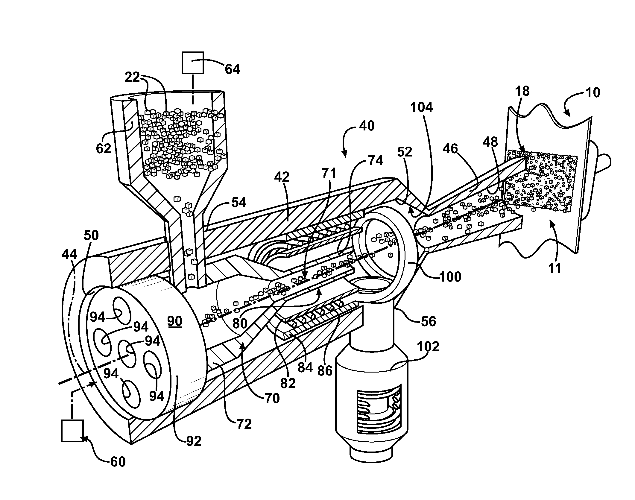
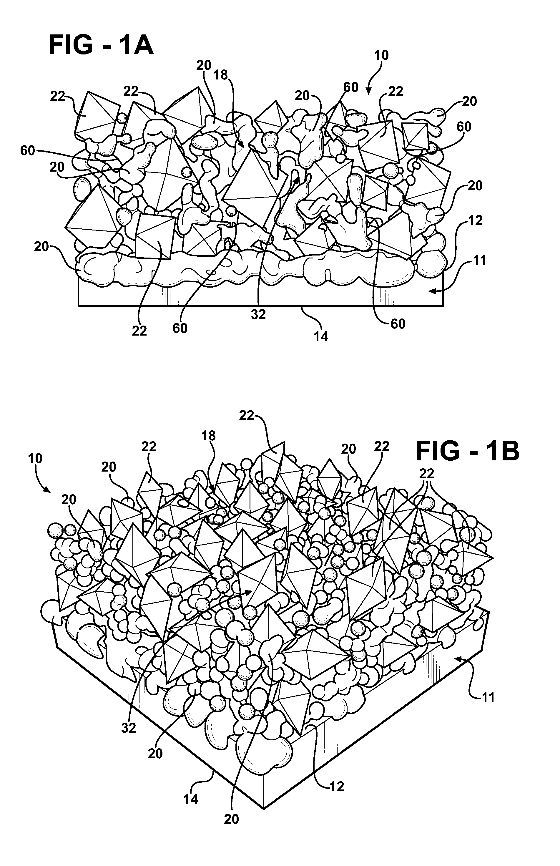
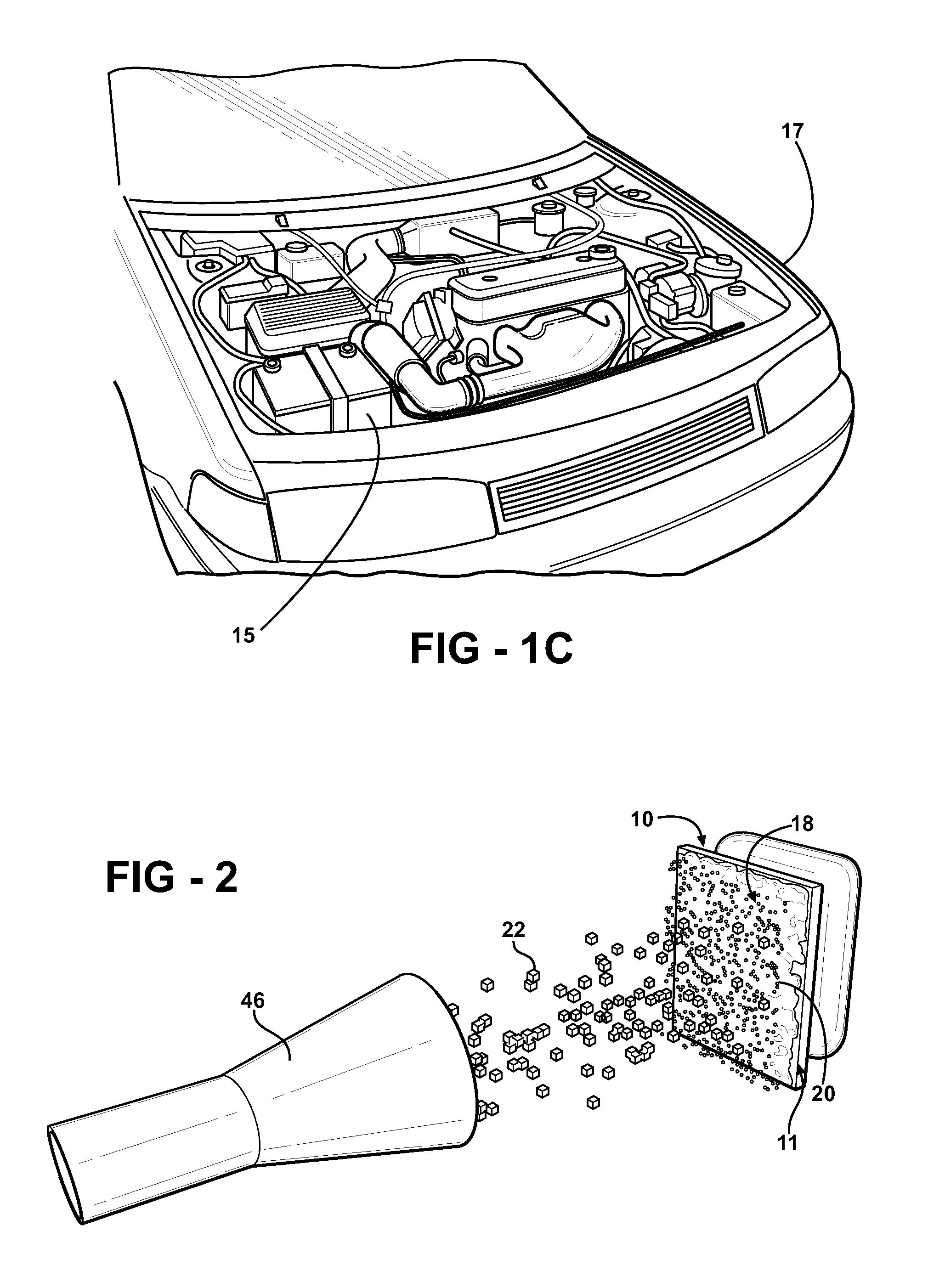
[0069] Referring to the Figures, wherein like numerals indicate like or corresponding parts, an electrode of the present invention is generally shown at 10. The electrode 10 of the present invention is formed from a metal tape, i.e. foil, generally indicated at 11 and shown fragmentally in FIGS. 1A to 1B, 3A through 3F, and 6A to 6B, is used to form a first electrode such as an anode and a second electrode such as cathode (both not shown), spaced by a separator and combined into a cell (not shown) for producing electric power without limiting the scope of the present invention. The metal current collector 11 of the first electrode and the second electrode has opposed sides 12 and 14, as best illustrated in a cross sectional view shown in FIG. 1A. The electrodes are combined into at least one cell used for a battery 15 for an automotive vehicle 17. The present inventive concept has various other applications including and not limited to high efficiency thin-film photovoltaic solar ce...


PUM

PropertyMeasurementUnit
Pressureaaaaaaaaaa
Pressureaaaaaaaaaa
Pressureaaaaaaaaaa

Abstract

A method and an apparatus of the present invention is used for the high-rate deposition of materials, such as carbon, silicon, metals, metal oxides, and the like, onto a metal substrate defined by a metal tape. The particles of the material are mixed with fluid and are injected against the metal tape at a high pressure and high velocity. The particles of the material form a current collection surface of the metal tape. The metal tape is used as cathode or anode combined with a separator to form a fuel cell of a secondary battery, metal-ceramic membranes, film composite metal-ceramic materials for electronic devices.

Description

RELATED APPLICATIONS [0001] This is a divisional application of a patent application Ser. No. 11 / 560,922 filed Nov. 17, 2006 which claims priority to a provisional patent application Ser. No. 60 / 780,240 filed on Mar. 8, 2006 and incorporated herewith in its entiretyFIELD OF THE INVENTION [0002] The subject invention relates to an apparatus and method for manufacturing an electrode for a cell having improved cell charged capacity, C-rate performance and recycling stability. BACKGROUND OF THE INVENTION [0003] The term “nanotechnology” generally refers to objects, systems, mechanisms and assemblies smaller than one ten of micron and larger than 1 nm. In recent years nanotechnology has been used to make products, that is, raw materials are processed and manipulated until the desired product is achieved. In contrast, nanotechnology mimics nature by building a product from the ground up using a basic building block—the atom. In nanotechnology atoms are arranged to create the material need...

Claims


Application Information

Patent Timeline
IPC IPC(8): B05B7/06B05C13/02B05D5/12H01M4/02H01M4/04H01M4/134H01M4/139H01M10/052
CPCC23C4/12Y10T29/53135C23C24/04H01G9/058H01G9/155H01G9/2027H01M4/04H01M4/0404H01M4/0419H01M4/134H01M4/139H01M4/661H01M4/75H01M4/886H01M10/052H01M2004/021Y02E10/542Y02E60/122Y02E60/13Y02E60/50Y02T10/7011Y02T10/7022Y10T29/49108Y10T29/49115C23C4/122C23C4/126Y02E60/10Y02P70/50Y02T10/70H01G11/84H01G11/86H01G11/28H01G11/22
Inventor KALYNUSHKIN, YEVGENNOVAK, PETER
Owner NANOENER TECH INC
Why Eureka
Try Eureka