Method and apparatus for remote sensing utilizing a reverse photoacoustic effect

a reverse photoacoustic and remote sensing technology, applied in the field of methods and machines for spectrometry, can solve the problems of cumbersome and expensive existing techniques based on laser detection and ranging (ladar) and hyper-spectral imaging, and is not ideal for the desired quick and widespread deploymen

Inactive Publication Date: 2007-09-27
UT BATTELLE LLC
View PDF7 Cites 19 Cited by
  • Summary
  • Abstract
  • Description
  • Claims
  • Application Information

AI Technical Summary

Benefits of technology

[0005] The method of the invention is based on detecting changes in acoustic signals that are produced at different levels of electromagnetic radiation due to absorption sprectra to identify a sample in a reliable fashion. The acoustic signals include an acoustic carrier wave train of pulses and the changes are changes in phase of individual pulses. An electromagnetic radiation source is used to transmit a filtered beam of light at varying wavelengths into the sample which increas

Problems solved by technology

However, current techniques available for such purpose are very limited as compared to that of contact or proximal detections.
Existing techniques based on laser detecting and ranging (LADAR) and hyper-spectral imaging are cumbersome, sophisticated and expensive and, therefore, are not ideal for the desired quick and widespread deployment.
Meanwhile, some highly light-scattering materials such as amorphous solid, powder, gel and suspension are not readily amenable to the conventional optical detection.
Unfortunately, the direct photoacoustic method is unsu

Method used


Image

  • Method and apparatus for remote sensing utilizing a reverse photoacoustic effect
  • Method and apparatus for remote sensing utilizing a reverse photoacoustic effect
  • Method and apparatus for remote sensing utilizing a reverse photoacoustic effect

Examples


Embodiment Construction

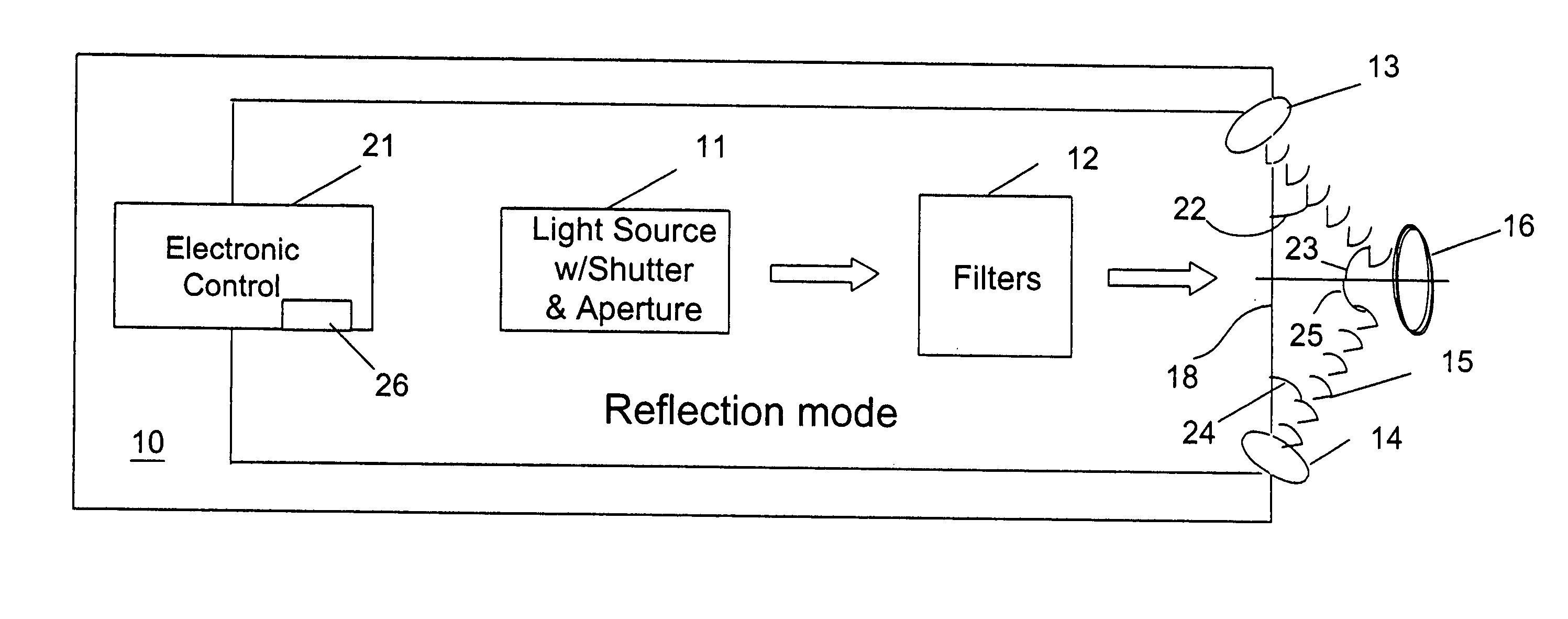
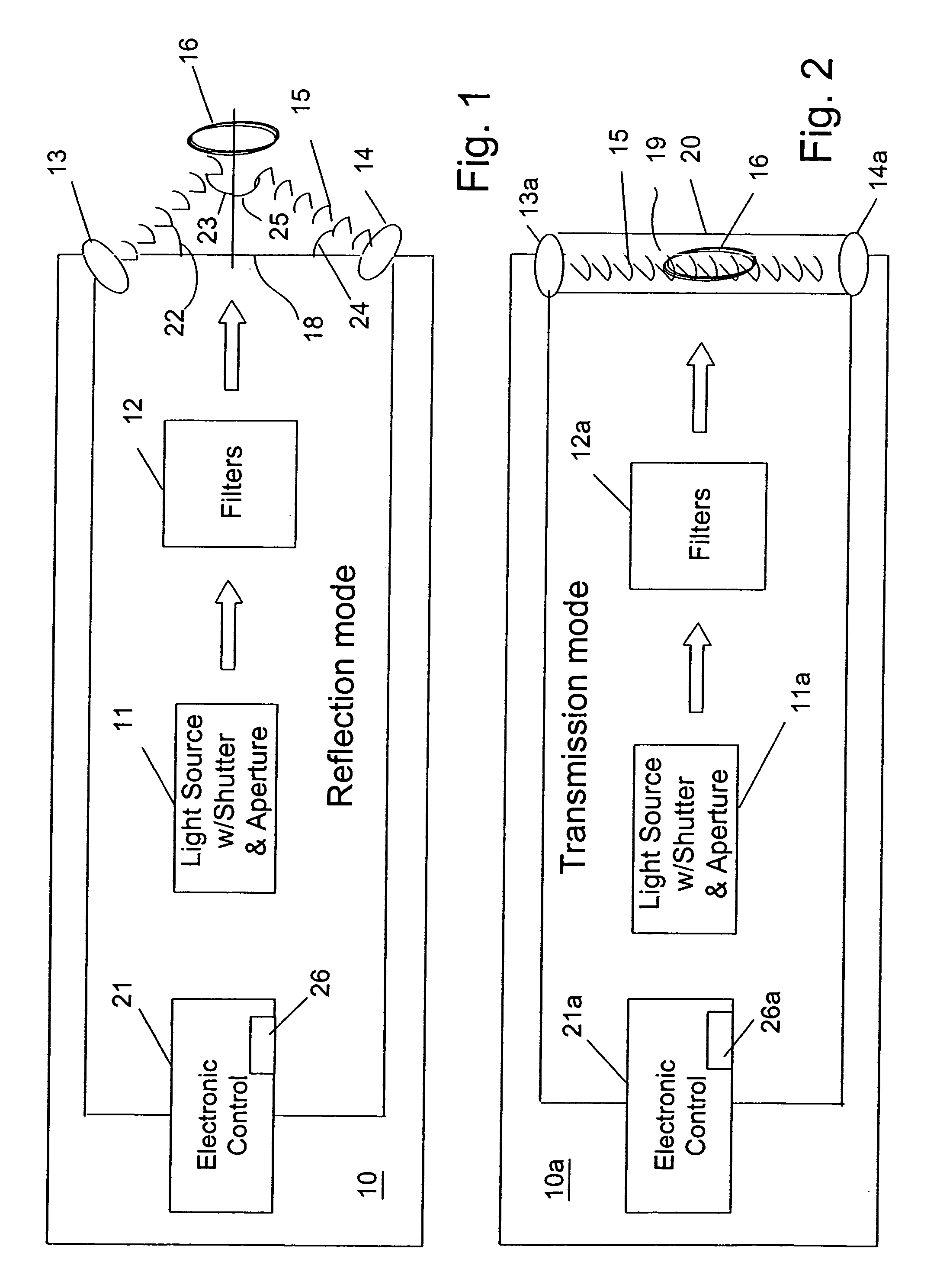
[0028] Referring to FIGS. 1 and 2, a machine 10 for practicing the method of the invention has a controllable light source 11 with a shutter and an aperture for controlling a duration and a width of a light beam. The machine 10 is provided with suitable user controls, such as on-off switches and a pushbutton or trigger-operated switch to momentarily apply the light source. One suitable example of a controllable light source 11 for the UV-visible region uses a 300-Watt Xenon lamp and accompanying power supply from Thermal Oriel. The light source 11 can also be a source for producing electromagnetic radiation in the near infrared range, the far infrared range, lasers of different wavelengths, and other tunable sources. A group of interference filters 12 is selectively and successively inserted along the path of the light to allow light with respective narrow wavelength bands to pass (Melles Griot). In test experiments, ethanol solutions of a plurality of dyes are used as adjustable li...


PUM


Abstract

A method and apparatus for identifying a sample, involves illuminating the sample with light of varying wavelengths, transmitting an acoustic signal against the sample from one side and receiving a resulting acoustic signal on another side, detecting a change of phase in the acoustic signal corresponding to the light of varying wavelengths, and analyzing the change of phase in the acoustic signal for the varying wavelengths of illumination to identify the sample. The apparatus has a controlled source for illuminating the sample with light of varying wavelengths, a transmitter for transmitting an acoustic wave, a receiver for receiving the acoustic wave and converting the acoustic wave to an electronic signal, and an electronic circuit for detecting a change of phase in the acoustic wave corresponding to respective ones of the varying wavelengths and outputting the change of phase for the varying wavelengths to allow identification of the sample. The method and apparatus can be used to detect chemical composition or visual features. A transmission mode and a reflection mode of operation are disclosed.

Description

TECHNICAL FIELD [0001] The field of the invention is methods and machines for spectrometry, particularly those methods and machines utilizing both light waves and acoustics. BACKGROUND ART [0002] An urgent and widespread need exists for the remote sensing and recognition of hazardous chemicals in various field environments. However, current techniques available for such purpose are very limited as compared to that of contact or proximal detections. Existing techniques based on laser detecting and ranging (LADAR) and hyper-spectral imaging are cumbersome, sophisticated and expensive and, therefore, are not ideal for the desired quick and widespread deployment. Meanwhile, some highly light-scattering materials such as amorphous solid, powder, gel and suspension are not readily amenable to the conventional optical detection. [0003] It has been reported that an interaction between electromagnetic radiation in the visible spectrum and a material can be detected photoacoustically or photo...

Claims


Application Information

Patent Timeline
IPC IPC(8): G01N29/04G01N9/24
CPCB82Y15/00G01N29/0681G01N29/075G01N2291/102G01N2291/0423G01N2291/044G01N2291/048G01N29/2418
Inventor SU, MINGTHUNDAT, THOMASHEDDEN, DAVID
Owner UT BATTELLE LLC
Why Eureka
Try Eureka