Method and Device for Recharging Using Portable Multi-Voltage Solar Cell

Inactive Publication Date: 2007-09-27
SOLEITEC
View PDF5 Cites 51 Cited by
  • Summary
  • Abstract
  • Description
  • Claims
  • Application Information

AI Technical Summary

Benefits of technology

[0022] The portable solar cell charger according to the present invention can easily change the polarities of the connecting terminal from (+, −) to (−, +) by turning a gutter clockwise or counterclockwise by about 90° so as to be applied to portable electronics products with various types of connecting terminal. Moreover, the portable charger adopts a screw-type connection method to correspond with various types of connecting terminal.
[0023] The portable solar cell charger according to the present invention includes a connecting line which can be wound on the body of the charger thereby ensuring small size and convenient usage, and a connector as a connecting terminal to connect an electronics product with the charger. A case to endure the connecting line and the connector, fun

Problems solved by technology

However, these batteries have to be recharged or exchanged into new ones after a definite period of time.
A user has to have access to a power source or auxiliary power supply to recharge a storage battery, but he/she may not recharge the storage battery if he/she is remote from a power source or has no charger.
However, those approaches have a problem that the solar cell module attached to a cellular phone can be used for only the cellular phone and is not compatible with other portable electric devices.
However, such a solar cell charger built in the case may not supply enough power for electric devices because the surface area of the solar cell plate to absorb sunlight is narrower as portabl

Method used


Image

  • Method and Device for Recharging Using Portable Multi-Voltage Solar Cell
  • Method and Device for Recharging Using Portable Multi-Voltage Solar Cell
  • Method and Device for Recharging Using Portable Multi-Voltage Solar Cell

Examples


Example

[0044] Reference will now be made in detail to the preferred embodiments of the present invention, examples of which are illustrated in the accompanying drawings.

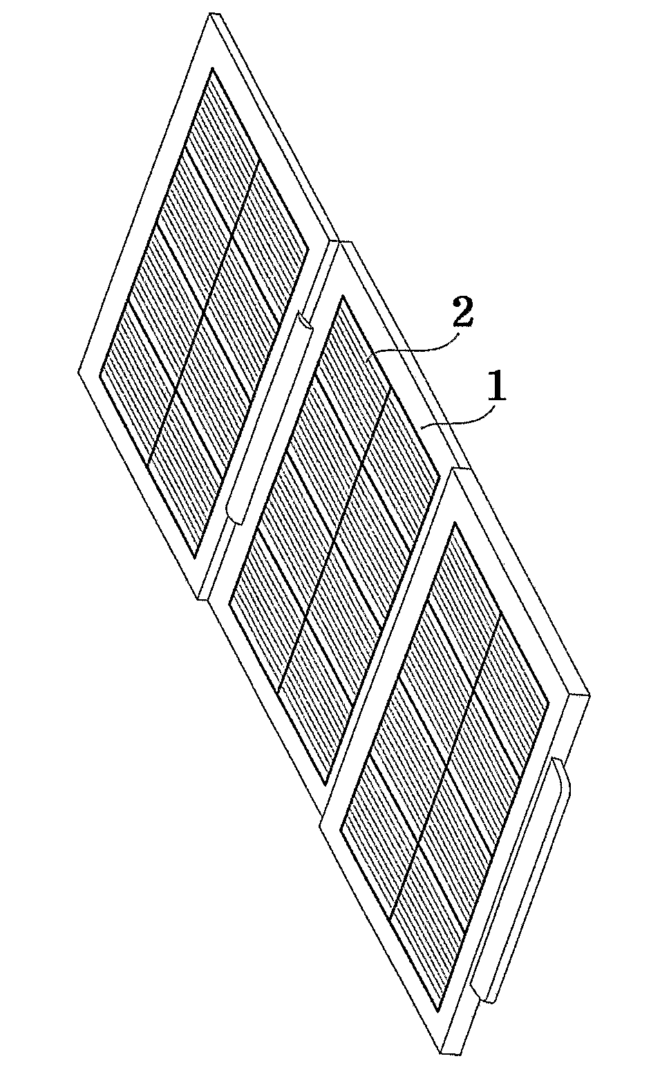
[0045]FIG. 5 is a schematic diagram of a portable solar cell charger according to an embodiment of the present invention. As shown in FIG. 5, a portable solar cell charger comprises at least one solar cell plate (1) on which a plurality of solar cells (2) are arranged in parallel / series and molded; a power selection part to select at least one power voltage from various power voltages by selectively coupling positive poles and negative poles of the arranged solar cells (2); a power connection part to provide the selected power voltage with a portable electronic device; and a portable case.

[0046]FIG. 6 is a schematic diagram illustrating the structure of the solar cell plate (1) according to an embodiment of the present invention and shows polarity connection between solar cells (2) in more detail. As shown in FIG. 6, the ...


PUM


Abstract

A portable solar cell charger and methods of charging electronic devices using the same are disclosed. A portable solar cell charger comprises at least one solar cell plate holding a plurality of solar cells; a film with reformed surface formed on the solar cell plate; a power control part supplying a load side with power after perceiving a voltage required from the load side; and a case holding the solar cell plate and the power control part. A method of charging an electronic device using a solar cell charger comprises perceiving a voltage required from a load side using a microprocessor; converting the perceived voltage using D/A converter; comparing the converted voltage with a voltage from a solar cell plate; integrating signals from a comparator and a pulse generator; adjusting the voltage from the solar cell plate; and supplying the voltage from the solar cell plate into the load side.

Description

TECHNICAL FIELD [0001] The present invention relates to a portable solar cell charger and methods of electricity charging devices using the same and, more particularly, a portable multi-voltage charging device with solar cells, which can recharge storage batteries or provide emergency power to portable electronic devices, such as a cellular phone, a personal digital assistant (PDA), a mini disc (MD) player, a compact disc (CD) player, an MP3 player, a notebook computer, a digital camera, and a camcorder, using solar cells which help the storage batteries to be continuously recharged under the given light condition. BACKGROUND ART [0002] Electronic devices which are widely used as necessities or commodities in today, such as cellular phones, MP3 players, MD players, notebook computers, portable radios, digital cameras, and camcorders, are supplied with power from storage batteries or dry batteries. However, these batteries have to be recharged or exchanged into new ones after a defin...

Claims


Application Information

Patent Timeline
IPC IPC(8): H02J7/00H02J7/35
CPCH01L31/0236H01L31/048H02J7/35H02S30/20Y02E10/50H02S20/00H02J7/355H02S20/30H02S10/40A22C9/00
Inventor LEE, MAN GEUN
Owner SOLEITEC
Why Eureka
Try Eureka