Transparent barrier sheet and preparation method thereof

Inactive Publication Date: 2007-09-27
KONICA MINOLTA MEDICAL & GRAPHICS INC
View PDF0 Cites 10 Cited by
  • Summary
  • Abstract
  • Description
  • Claims
  • Application Information

AI Technical Summary

Benefits of technology

[0022]The thickness of a substrate sheet can appropriately be chosen according to the use of the transparent barrier sheet of the invention. Taking into account capability as a packaging material, there can optionally be used not only a single resin sheet but also a layered sheet composed of combined sheets differing in quality. Further, taking into account processability in formation of a transparent inorganic layer or a transparent organic layer, the substrate thickness is preferably from 6 to 400 nm in practical use, and more preferably from 25 to 100 nm.
[0023]In the case of the use for electronic devices such as a liquid crystal display element, a dye type solar battery, an organic or inorganic EL, electronic paper and a fuel cell, the substrate thickness is appropriately chosen according to the use thereof. In the case of the use instead of a glass substrate, for instance, a thickness of 50 to 800 μm is preferred to fit the subsequent preparation process of glass substrate specification, and a thickness of 50 to 400 n is more preferred.
[0024]When taking into account mass production of the transparent barrier sheet of the invention, a continuous long length of film is preferred to enable continuous formation of a transparent inorganic layer and a transparent organic layer on a substrate sheet.
[0025]In one preferred embodiment of the invention, a transparent primer layer is provided on the substrate layer.
[0026]A transparent primer layer is provided on the substrate sheet to enhance adhesion to the layer provided on the primer layer and achieve smoothness of the layer. A transparent primer layer can be formed by coating a solution of resin dissolved in solvents, followed by drying. After being dried, a curing reaction may be undergone. Alternatively, a metal alkoxide, a ultraviolet curing resin, an electron beam curing resin

Problems solved by technology

However, such packaging materials using a metal foil as a gas-barrier layer, which exhibit enhanced gas barrier capability and are barely affected by temperature or humidity, have several disadvantages such that the contents cannot be viewed through the packaging material and a metal detector cannot be employed for inspection of the contents, aris

Method used


Image

  • Transparent barrier sheet and preparation method thereof
  • Transparent barrier sheet and preparation method thereof
  • Transparent barrier sheet and preparation method thereof

Examples


Example

Example 1

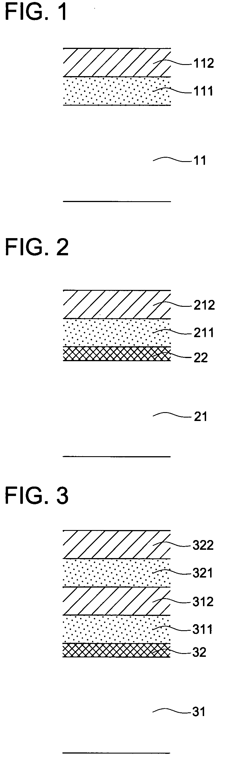
[0075]A 100 μm thick polyether sulfone film (Sumilight FS-530, produced by Sumitomo Bakelight Co., Ltd.) was prepared as a substrate sheet. One side of the sheet was subjected to a corona discharge treatment and further thereon, a coating composition composed of 98 parts of methyl ether and 2 parts of diphenyl-4-thiophenoxysulfonium hexafluoroantimonate as an initiator was coated at a coating thickness of 0.5 μm. Then, using an ultraviolet exposure apparatus (a conveyor-fitted UV curing apparatus, produced by Iwasaki Denki) the coated surface was exposed to ultraviolet rays in an atmosphere at a sufficient dose to react the composition and cured to form a transparent primer layer. The surface of the transparent primer layer was measured at five sites within an area 200 μm×200 μm by using a noncontact 3D surface measuring apparatus (WYKO NT1100, produced by Veeco). Surface roughness (Ra) was analyzed using a self-contained surface analysis software. Average surface roughness...

Example

Example 2

[0084]A substrate sheet provided with transparent primer layers on both sides was prepared. On both sides of a 125 μm thick biaxially stretched polyethylene terephthalate film (Cosmoshine A-4300, produced by Toyobo) was coated with the same coating composition as used in Example 1 and exposed to ultraviolet rays to be cured to form a 0.3 μm thick transparent primer layer. The surface of the transparent primer layer was measured at five sites by using a noncontact 3D surface measuring apparatus (WYKO NT1100, produced by Veeco) and the average surface roughness (Ra) was 3.5 nm.

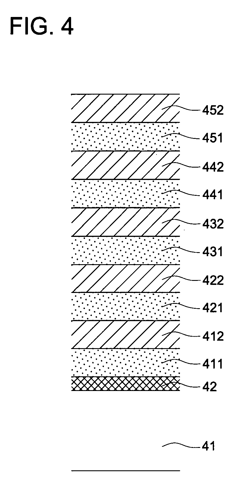
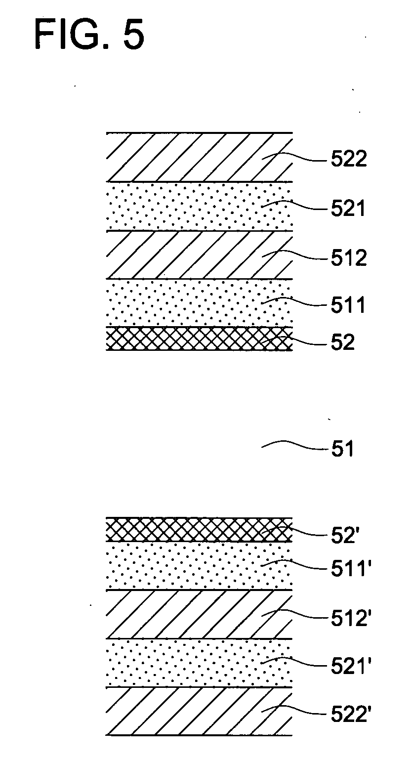
[0085]Then, transparent barrier sheets of the invention, 2-A through 2-E were prepared in the manners 1) and 2) described below. The thus prepared transparent barrier sheets were evaluated with respect to barrier capability and bending resistance similarly to Example 1. Results obtained are shown in Table 2.

1) Formation of Inorganic Layer:

[0086]Using a film deposition apparatus according to the process ...

Example

Example 3

[0090]One side of a 100 μm thick biaxially stretched polyethylene terephthalate film (Teonex Q65, produced by Teijin) was subjected to a corona discharge treatment to prepare a substrate sheet. The substrate sheet was placed into a vacuum vessel and the inside of the vessel was evacuated to a level of 10−4 Pa, and 1,4-butanediol glycidyl ether and 1,3-diaminopropane (produced by Tokyo Kasei) were each introduced as separate deposition sources and flash heating was started. After completing evaporation of impurities, a deposition shutter was opened to allow deposition and polymerization on the substrate sheet to form a transparent primer layer C. The surface of the transparent primer layer was measured at five sites by using a noncontact 3D surface measurement apparatus (WYKO NT1100, produced by Veeco) and the surface roughness (Ra) was 2.0 nm.

[0091]Subsequently, a transparent inorganic layer A, as described in 3) below and a transparent organic layer B, as described in 4) b...


PUM

PropertyMeasurementUnit
Temperatureaaaaaaaaaa
Thicknessaaaaaaaaaa

Abstract

A transparent barrier sheet comprising on one side of a substrate sheet at least one transparent inorganic layer and at least one transparent organic layer, wherein an outermost layer of the inorganic layer and the organic layer exhibits a surface roughness Ra of not more than 5 nm and the transparent inorganic layer exhibits a thickness of 20 nm to 500 nm, and the transparent barrier sheet meeting the requirement:
0.5≦d2/d1≦10
wherein d1 is a thickness of the inorganic layer and d2 is a thickness of the organic layer.

Description

[0001]This application claims priority from Japanese Patent Application No. JP2006-082438 filed on Mar. 24, 2006, which is incorporated hereinto by reference.FIELD OF THE INVENTION[0002]The present invention relates to a transparent packaging barrier sheet used for packaging in the field of food and medicines or a transparent barrier sheet for use in electronic instrument-related components, and in particular to a transparent barrier sheet exhibiting extremely low permeability of gas such as oxygen or water vapor and a preparation method thereof.BACKGROUND OF THE INVENTION[0003]Recently, packaging materials used for packaging foods or medicines require transparency for confirmation of contents and gas-barrier capability to inhibit adverse influences due to gases deteriorating contents, such as permeated oxygen, water vapor or the like. There were employed packaging materials using, as a gas-barrier layer, a metal foil composed of metals such as aluminum or the like when relatively h...

Claims


Application Information

Patent Timeline
IPC IPC(8): B32B18/00B32B9/00B32B27/00G11B5/64C23C16/00B05D1/36B05D7/00B32B19/00C08J7/043C08J7/044C08J7/046C08J7/048
CPCC08J7/18C08J2367/02C08J7/045Y10T428/24355C08J2429/00Y10T428/265C08J2381/06C08J7/0423C08J7/048C08J7/043C08J7/046C08J7/044
Inventor TAKEYAMA, TOSHIHISA
Owner KONICA MINOLTA MEDICAL & GRAPHICS INC
Why Eureka
Try Eureka