Red phosphorescent compound and organic electroluminescent device using the same

Active Publication Date: 2007-09-27
LG DISPLAY CO LTD
View PDF5 Cites 378 Cited by
  • Summary
  • Abstract
  • Description
  • Claims
  • Application Information

AI Technical Summary

Benefits of technology

[0014]An object of the present invention is to provide a red phosphorescent compound that exhibits desirable chromaticit

Problems solved by technology

As shown in FIG. 1, as the color purity of an organic EL device using a red phosphorescent material becomes higher (i.e. as the x-values on CIE chromaticity coordinat

Method used


Image

  • Red phosphorescent compound and organic electroluminescent device using the same
  • Red phosphorescent compound and organic electroluminescent device using the same
  • Red phosphorescent compound and organic electroluminescent device using the same

Examples


synthesis example

1. Synthesis of 3-(3,5-dimethylphenyl)-4-methylisoquinoline

[0034]

[0035]Propane-2-yl-benzene (100 mmol), acetic acid palladium (2.7 mmol), triphenylphosphine (5 mmol), and sodium carbonate (50 mmol) were put in a dried two-neck round-bottom flask and dissolved in DMF (100 ml). Subsequently, tert-butyl-(2-iodo-benzylidene)amine (50 mmol) was added thereto. The resulting solution was stirred in a bath at 100° C. for 24 hours. After completion of the reaction, the temperature was allowed to cool to room temperature. The reaction mixture was extracted with ether and saturated NH4Cl. The extract was distilled under reduced pressure. The resulting residue was purified by silica gel column chromatography (hexane: EtOAc=5:1) to yield 3-(3,5-dimethylphenyl)-4-methylisoquinoline.

[0036]2. Synthesis of Dichloro-Crosslinked Dimer Complex

[0037]Iridium (III) chloride hydrate (1 mmol), 3-(3,5-dimethylphenyl)-4-methylisoquinoline (2.5 mmol), and a mixed solvent (3:1) of ethoxyethanol and distilled wa...

example 1

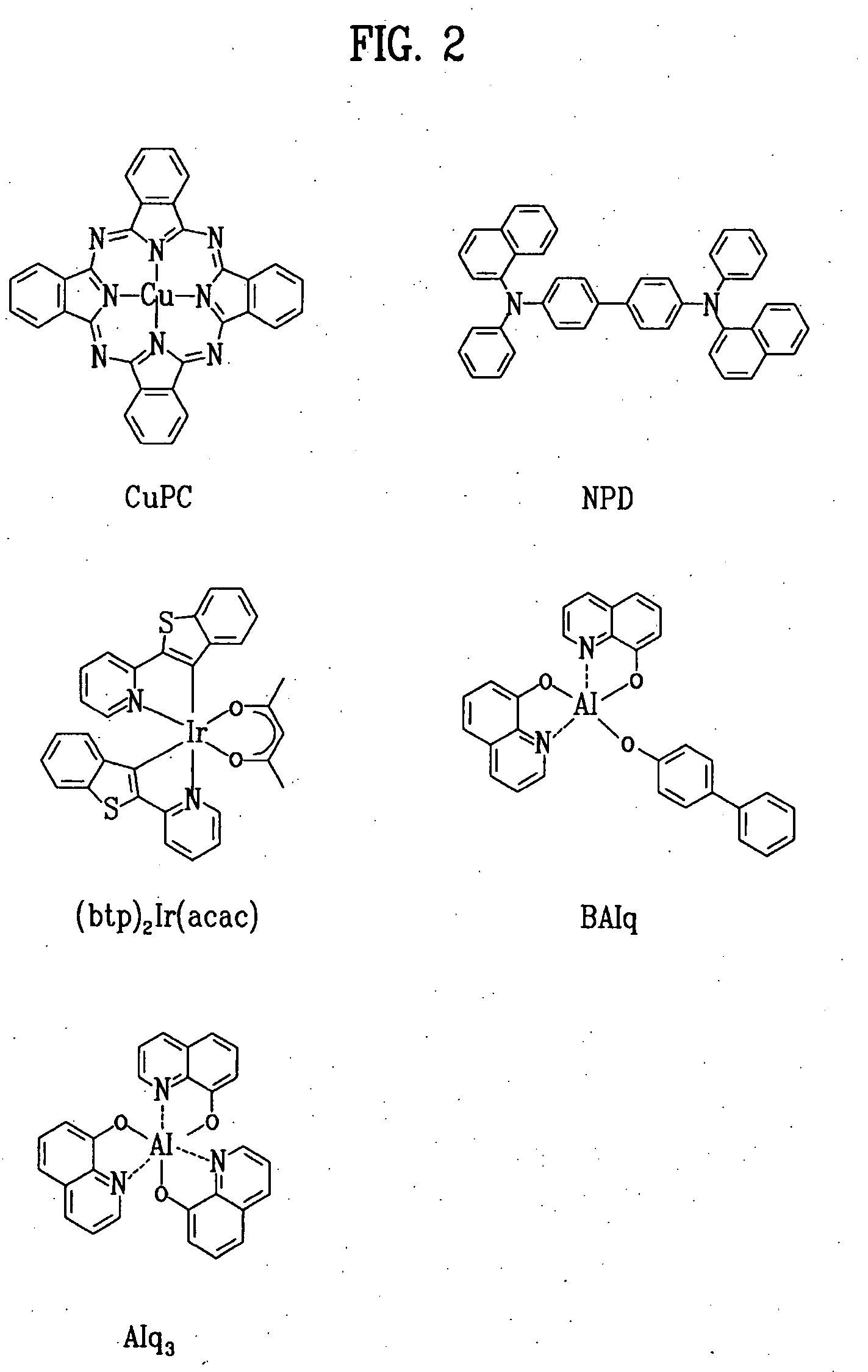
[0041]An ITO-coated glass substrate was patterned to have a light-emitting area of 3 mm×3 mm, followed by cleaning. After the patterned substrate was disposed in a vacuum chamber, the standard pressure of the chamber was adjusted to 1×10⁻⁶ torr. CuPc (200 Å), NPD (400 Å), BAlq+A-1 (7%) (200 Å), Alq3 (300 Å), LiF (5 Å) and Al (1,000 Å) were sequentially deposited on the ITO glass substrate to fabricate an organic EL device.

[0042]The luminance of the organic EL device thus fabricated was 1,326 cd / m2 at an electric current of 0.9 mA and a voltage of 6.1 V. At this time, the CIE chromaticity coordinates were x=0.601 and y=0.327. The lifetime (defined as the time taken before the luminance of the organic EL device decreases to half its initial value) of the organic EL device was 3,700 hours at 2,000 cd / m2.

example 2

[0043]An ITO-coated glass substrate was patterned to have a light-emitting area of 3 mm×3 mm, followed by cleaning. After the patterned substrate was disposed in a vacuum chamber, the standard pressure of the chamber was adjusted to 1×10⁻⁶ torr. CuPc (200 Å), NPD (400 Å), BAlq+A-2 (7%) (200 Å), Alq3 (300 Å), LiF (5 Å) and Al (1,000 Å) were sequentially deposited on the ITO glass substrate to fabricate an organic EL device.

[0044]The luminance of the organic EL device thus fabricated was 1,420 cd / m2 at an electric current of 0.9 mA and a voltage of 5.7 V. At this time, the CIE chromaticity coordinates were x=0.592 and y=0.330. The lifetime (defined as the time taken before the luminance of the organic EL device decreases to half its initial value) of the organic EL device was 4,200 hours at 2,000 cd / m2.


PUM

PropertyMeasurementUnit
Timeaaaaaaaaaa
Percent by massaaaaaaaaaa
Luminanceaaaaaaaaaa

Abstract

Disclosed herein is a red phosphorescent compound represented by Formula 1 below:
wherein
is
R1 is selected from the group consisting of C1-C4 alkyl and C1-C4 alkoxy; R2, R3, R4 and R5 are independently selected from the group consisting of
hydrogen, C1-C4 alkyl and C1-C4 alkoxy; and
is selected from the group consisting of 2,4-pentanedione, 2,2,6,6,-tetramethylheptane-3,5-dione, 1,3-propanedione, 1,3-butanedione, 3,5-heptanedione, 1,1,1-trifluoro-2,4-pentanedione, 1,1,1,5,5,5-hexafluoro-2,4-pentanedione and 2,2-dimethyl-3,5-hexanedione.
Further disclosed herein is an organic electroluminescent (EL) device using the red phosphorescent compound.

Description

[0001]This application claims the benefit of Korean Patent Application No. 10-2006-0026630 filed on Mar. 23, 2006, which is hereby incorporated by reference as if fully set forth herein.BACKGROUND OF THE INVENTION[0002]1. Field of the Invention[0003]The present invention relates to a red light-emitting phosphorescent compound (hereinafter, referred to simply to as a ‘red phosphorescent compound’) and an organic electroluminescent (EL) device using the same. More particularly, the present invention relates to a red phosphorescent compound and an organic electroluminescent device realizing an improvement in color purity by using the red phosphorescent compound as a dopant of a light-emitting layer.[0004]2. Discussion of the Related Art[0005]Since electroluminescent devices are self-luminous display devices, they have the advantages of a wide viewing angle, a large contrast ratio, and a high response speed. Electroluminescent devices are divided into inorganic electroluminescent device...

Claims


Application Information

Patent Timeline
IPC IPC(8): H01L51/54C09K11/06
CPCC09K11/06C09K2211/1029C09K2211/1092H05B33/14H01L51/0081H01L51/0085H01L51/5016C09K2211/185H10K85/324H10K85/342H10K50/11H10K2101/10C09K11/87Y10S428/917
Inventor KIM, JUNG KEUNSEO, JEONG DAELEE, KYUNG HOONPARK, CHUN GUNJEONG, HYUN CHEOLBIN, JONG KWANPIEH, SUNG HOON
Owner LG DISPLAY CO LTD
Why Eureka
Try Eureka