Optical tomography method & device

a tomography and optical technology, applied in the field of tomography methods and devices, can solve the problems of reducing the difficulty of system installation, and reducing the scattering effect,

Inactive Publication Date: 2007-10-11
CHIEN CHOU
View PDF3 Cites 27 Cited by
  • Summary
  • Abstract
  • Description
  • Claims
  • Application Information

AI Technical Summary

Benefits of technology

[0033]The present invention employs the principle of heterodyne interference, so that aberration and dispersion of beams with the same transmission path automatically counterbalance each other. Moreover, by using a moving focusing lens to perform axial scanning, the difficulty involved in system installation can be reduced. Besides, a focusing lens with a large numerical aperture can be used to obtain a sectioning image with high lateral resolution, thereby solving the problem of the prior art, which fails to address both the axial resolution and the lateral resolution. In addition, the present invention is particularly suited for measuring a scattering medium due to the depolarization effect in the scattering medium of the two-frequency mutually correlated low-coherence photon pairs, and due to the use of a low-coherence beam. Thus, the scattered low-coherence two-frequency photon-pair beam cannot generate heterodyne interference, thereby reducing the scattering effect by a band pass filter in the signal processing unit. Moreover, since the signal beam is focused via the lens, and since the signal beam reflected by an off-focus plane of the focusing lens is further filtered by the pinhole, the scattering effect can also be reduced to obtain a sectioning image with high axial resolution.

Problems solved by technology

Furthermore, because OCT uses a low-coherence light source, the coherence length is very short.
Such a resolution can only permit identification of the form of bio-tissue and any mutation in the form of the bio-tissue caused by disease.
However, the laser system is quite expensive and complicated.
However, since it is not possible to positively know the changes in the refractivity of the medium 11, only an approximate refractivity can be used as the refractivity of the compensator.
Consequently, the axial resolution deteriorates.
Furthermore, because the medium 11 will scatter the signal beam 101, especially when the medium 11 is a scattering medium, light reflected from the medium 11 at other depth positions can also pass through the pinhole, thereby resulting in a reduction in the signal to noise ratio (SNR) of the heterodyne interference signal, which affects adversely the quality of the sectioning image.

Method used


Image

  • Optical tomography method & device
  • Optical tomography method & device
  • Optical tomography method & device

Examples


Embodiment Construction

[0044]Before the present invention is described in greater detail, it should be noted that like elements are denoted by the same reference numerals throughout the disclosure.

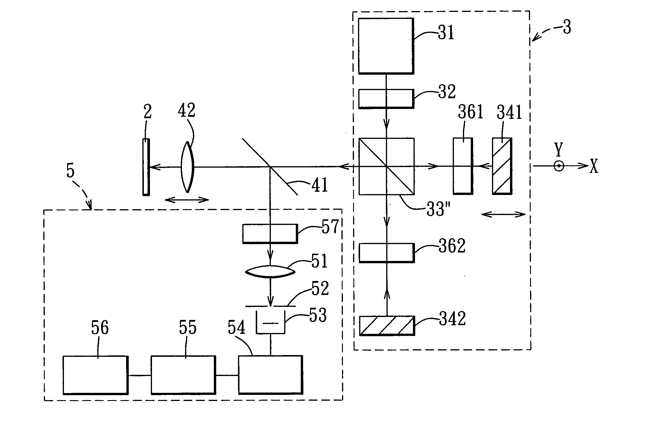
[0045]Referring to FIG. 4, the first preferred embodiment of an optical tomography device for implementing the method of the present invention is shown to include a two-frequency beam generating unit 3, a relay beam splitter 41, a focusing lens 42, and a signal processing unit 5.

[0046]The two-frequency beam generating unit 3 includes a low-coherence light source 31, such as a super luminescent diode (SLD), and a polarizer 32 capable of adjusting polarization angles for generating a 45° linear polarized beam. The linear polarized beam is split by a polarizing beam splitter (PBS) 33″ into a p-polarization beam and an s-polarization beam, which are hereinafter referred to as a P wave and an S wave, respectively. The S wave is passed through a quarter wave plate (QWP) 361 having an azimuth angle of 45° to become a c...


PUM


Abstract

A method for optical tomography is adapted to measure a medium, and includes the following steps: (A) generating a two-frequency mutually correlated low-coherence beam, an optical path difference of the beam being smaller than a coherence length; (B) focusing the beam on different depth positions of the medium such that the beam becomes a signal beam after being reflected by the medium; and (C) analyzing the signal beam reflected by the medium using a signal processing unit that includes a lens and a pinhole located at a focal point of the lens so as to obtain a sectioning image of the medium.

Description

CROSS-REFERENCE TO RELATED APPLICATION[0001]This application claims priority of Taiwanese Application No. 095112404, filed on Apr. 7, 2006.BACKGROUND OF THE INVENTION[0002]1. Field of the Invention[0003]The invention relates to a tomography method and device, more particularly to an optical tomography method and device.[0004]2. Description of the Related Art[0005]Optical coherence tomography (OCT) scanners are currently very useful tomography scanners applied to ophthalmology, dermatology, cardiology, and other related medical diagnosis, because they can provide clear sectioning images required for diagnosing various illnesses. Moreover, compared to other non-invasive medical imaging techniques, such as computer tomography (CT), magnetic resonance imaging (MRI), and ultrasound, OCT can provide a better spatial resolution.[0006]Basically, OCT uses an interferometer with a low-coherence light source. The interferometer will interfere only when an optical path difference between a sign...

Claims


Application Information

Patent Timeline
Patent Type & Authority Applications(United States)
IPC IPC(8): G01B9/02
CPCA61B5/0066A61B5/0073A61B5/0261G01B2290/70G01B9/02002G01B9/02091G01B9/02097G01N21/4795
Inventor CHOU, CHIENKUO, WEN-CHUAN
Owner CHIEN CHOU
Why Eureka
Try Eureka