Method and apparatus for extending equipment uptime in ion implantation

a technology of ion implantation and equipment, which is applied in the manufacture of electrode systems, discharge tube cleaning, electric discharge tube/lamp manufacture, etc., can solve the problems of serious contamination effect, interference with the successful operation of the source, and severe ion beam quality damage, so as to reduce equipment down time and increase service life

a technology of ion implantation and equipment, which is applied in the manufacture of electrode systems, discharge tube cleaning, electric discharge tube/lamp manufacture, etc., can solve the problems of serious contamination effect, interference with the successful operation of the source, and severe ion beam quality damage, so as to reduce equipment down time and increase service life

US20070241689A1Inactive Publication Date: 2007-10-18SEMEQUIP

Image

  • Method and apparatus for extending equipment uptime in ion implantation
  • Method and apparatus for extending equipment uptime in ion implantation
  • Method and apparatus for extending equipment uptime in ion implantation

Examples


Embodiment Construction

Novel Ion Beam-Generating System

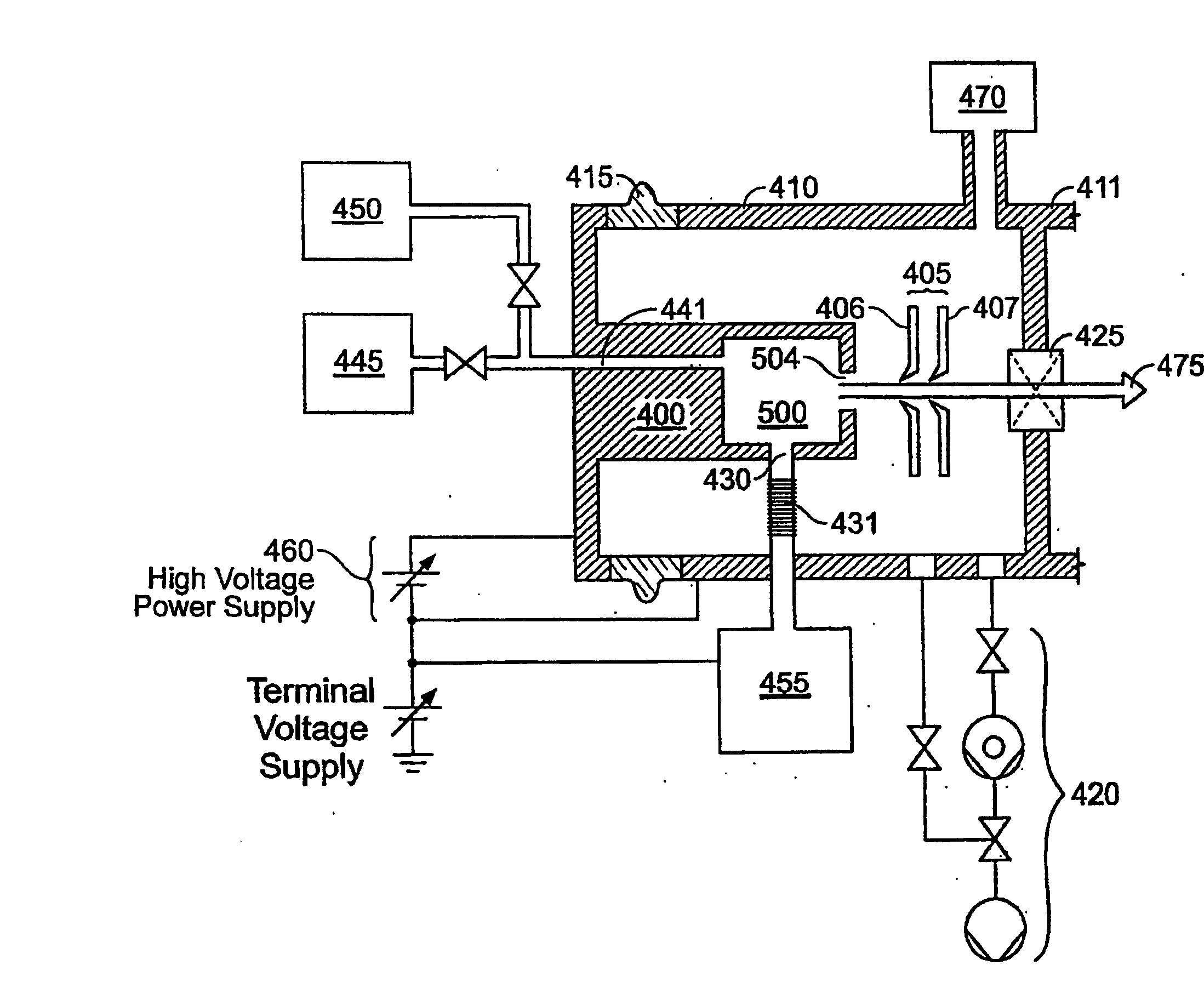
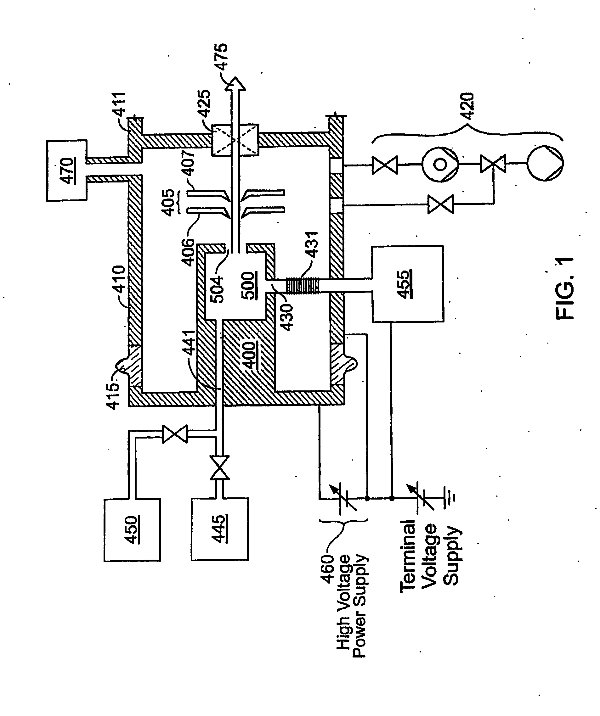
[0136]FIG. 1 shows an ion beam-generating system. As shown in this example, it is adapted to produce an ion beam for transport to an ion implantation chamber for implant into semiconductor wafers or flat-panel displays. Shown are ion source 400, extraction electrode 405, vacuum housing 410, voltage isolation bushing 415 of electrically insulative material, vacuum pumping system 420, vacuum housing isolation valve 425, reactive gas inlet 430, feed gas and vapor inlet 441, vapor source 445, feed gas source 450, reactive gas source 455, ion source high voltage power supply 460, and resultant ion beam 475. An ion beam transport housing is indicated at 411. The ion source 400 is constructed to provide cluster ions and molecular ions, for example the borohydride ions B10Hx+, B10Hx−, B18Hx+, and B18Hx− or, or in addition, more conventional ion beams such as P+, As+, B+, In+, Sb+, Si+, and Ge+. Ion source 400 may be a Bernas-style arc-discharge ion source, ...


PUM

PropertyMeasurementUnit
vapor pressureaaaaaaaaaa
internal surface areaaaaaaaaaaa
volumeaaaaaaaaaa

Abstract

The service lifetime of an ion source is enhanced or prolonged by the source having provisions for in-situ etch cleaning of the ion source and of an extraction electrode, using reactive halogen gases, and by having features that extend the service duration between cleanings. The latter include accurate vapor flow control, accurate focusing of the ion beam optics, and thermal control of the extraction electrode that prevents formation of deposits or prevents electrode destruction. An apparatus comprised of an ion source for generating dopant ions for semiconductor wafer processing is coupled to a remote plasma source which delivers F or Cl ions to the first ion source for the purpose of cleaning deposits in the first ion source and the extraction electrode. These methods and apparatus enable long equipment uptime when running condensable feed gases such as sublimated vapor sources, and are particularly applicable for use with so-called cold ion sources. Methods and apparatus are described which enable long equipment uptime when decaborane and octadecaborane are used as feed materials, as well as when vaporized elemental arsenic and phosphorus are used, and which serve to enhance beam stability during ion implantation.

Description

FIELD OF THE INVENTION [0001] The present invention relates to producing ion beams in which one or more gaseous or vaporized feed materials is ionized in an ion source. It also relates to a method and apparatus for operating an ion source to produce an ion beam for ion implantation of semiconductor substrates and substrates for flat panel displays. In particular the invention concerns extension of the productive time (i.e. the “uptime”) of systems that produce ion beams. BACKGROUND [0002] Ion beams are produced from ions extracted from an ion source. An ion source typically employs an ionization chamber connected to a high voltage power supply. The ionization chamber is associated with a source of ionizing energy, such as an arc discharge, energetic electrons from an electron-emitting cathode, or a radio frequency or microwave antenna, for example. A source of desired ion species is introduced into the ionization chamber as a feed material in gaseous or vaporized form where it is ex...

Claims


Application Information

Patent Timeline
18 Oct 2007
Publication
US20070241689A1
IPC
H01J3/00; H01J; H01J7/24; H01J37/08; H01J37/317
CPC
C23C14/48; C23C14/564; H01J9/38; H01J27/02; H01J2237/022; H01J37/08; H01J37/3171; H01J2209/017
Inventors
HORSKY, THOMAS N.; MILGATE, ROBERT W. III