Wireless communication apparatus

a communication device and wireless technology, applied in the direction of receivers, fixed transformers, near-field systems using receivers, etc., can solve the problems of inability to perform high-speed data communication, power consumption, and increased size, and achieve high reliability, large screen, and the effect of reducing the portability of the wireless communication terminal

Inactive Publication Date: 2007-11-01
138 EAST LCD ADVANCEMENTS LTD
View PDF6 Cites 21 Cited by
  • Summary
  • Abstract
  • Description
  • Claims
  • Application Information

AI Technical Summary

Benefits of technology

[0011] An advantage of some aspects of the invention is to provide a wireless communication apparatus that can transmit power without causing poor contact, suppress an increase in size of a circuit, and implement high-speed data communication in a wireless manner.
[0013] With this configuration, power can be transmitted in a non-contact manner between the wireless transmitting unit and the wireless receiving unit, and the carrier waves can be generated in the wireless transmitting unit and the wireless receiving unit on the basis of the same power carrier wave clock. For this reason, even though wireless data communication is performed between the wireless transmitting unit and the wireless receiving unit, a local oscillator for generating a reference clock, or an automatic frequency adjusting circuit or an A / D converter for adjusting a shift in frequency of the reference clock on transmitting and receiving sides is not required. Therefore, an increase in size of a circuit can be suppressed, high-speed data communication can be implemented in a wireless manner, and power can be transmitted without causing poor contact.
[0014] An overhead for adjusting the shift in frequency of the carrier wave between the transmitting and receiving sides can be eliminated, and throughput upon wireless communication can be improved. In addition, complete synchronous detection can be implemented, and optimum communication quality can be maintained.
[0019] With this configuration, an increase in size of a circuit can be suppressed, and data communication can be performed between the primary module and the secondary module in a wireless manner. Further, an increase in costs, power consumption, and size can be suppressed, and high-speed communication of mass data can be performed. In addition, power can be transmitted without causing poor contact.
[0021] With this configuration, even though the size of display data to be transmitted from the first casing to the second casing is increased with large screen and large definition of the display unit mounted on the second casing, the display data can be transmitted to the display unit at high speed without complicating the configuration of the connection unit, and power can be transmitted without causing poor contact. For this reason, a small and thin wireless communication terminal and high reliability can be implemented. In addition, a wireless communication terminal having a large screen and multi-functionality can be implemented without impairing portability of the wireless communication terminal.

Problems solved by technology

However, in the method that transmits power in the non-contact manner for the sake of charging or the like, in order to transfer mass image data stored in the information terminal apparatus, such as a digital camera or a cellular phone with a camera, to a personal computer, a connector for wired communication, such as a USB, is required, and thus there is a problem in that the above method cannot cope with transmission of mass image data.
In the methods disclosed in JP-A-9-103037 and JP-A-2005-73350, data communication is performed through a power transmission device, such as an electromagnetic induction coil, and thus there is a problem in that high-speed data communication cannot be performed.
In the method disclosed in JP-A-6-133476, a wireless machine is merely provided alone separately from the non-contact power transmission device, and thus there is a problem in that costs, power consumption, and the size are increased.
Accordingly, there is a problem in that the size of the circuit is increased.

Method used


Image

  • Wireless communication apparatus
  • Wireless communication apparatus
  • Wireless communication apparatus

Examples


first embodiment

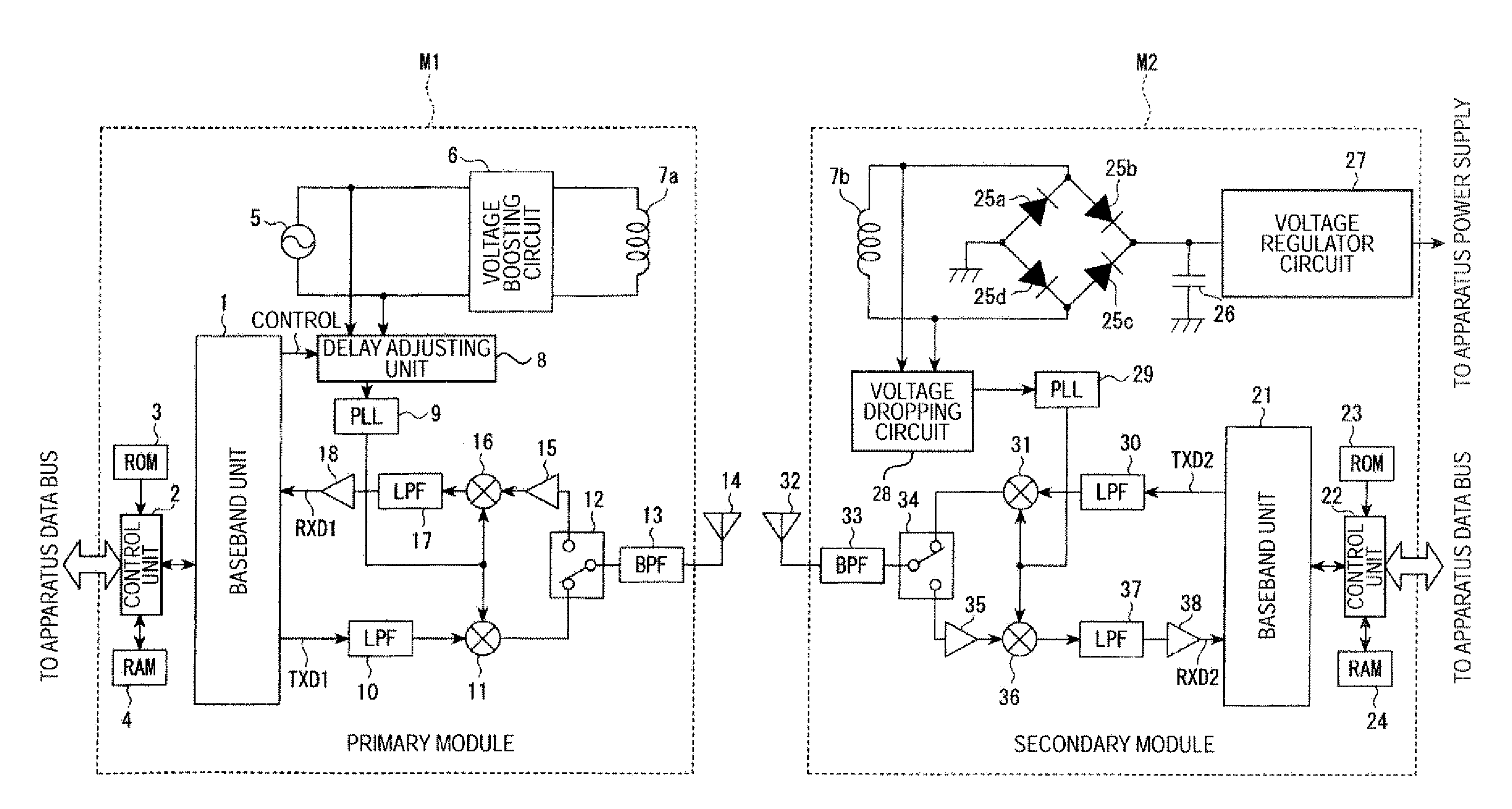
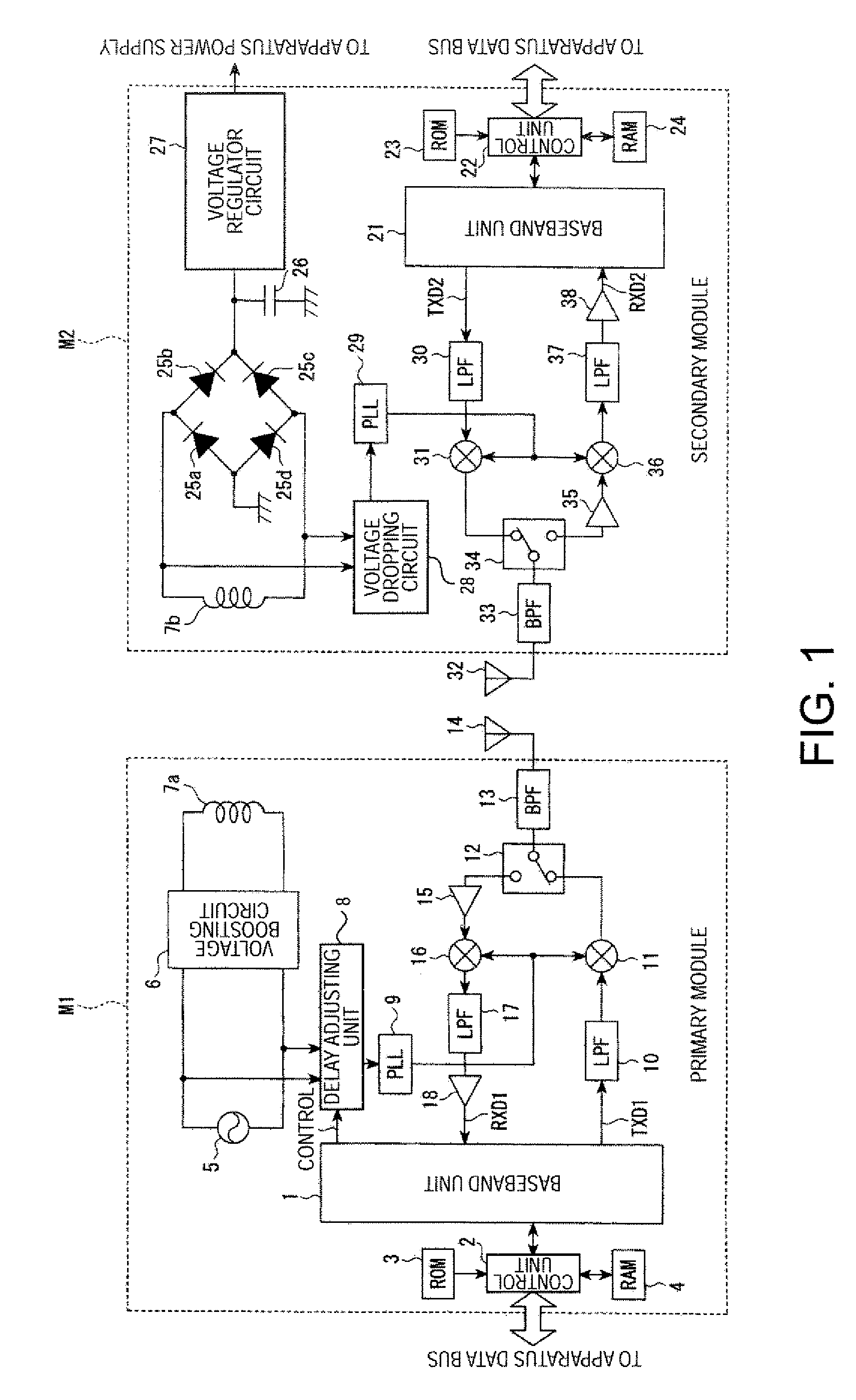
[0028]FIG. 1 is a block diagram showing the schematic configuration of a wireless communication apparatus according to the invention.

[0029] Referring to FIG. 1, in a primary module M1, a baseband unit 1 that performs a baseband signal processing, a control unit 2 that performs the control of the baseband unit 1 and the like, a ROM 3 that stores various programs for operating the primary module M1, a RAM 4 that provides a work area when the control unit 2 executes a processing or stores the processing result, a power carrier wave clock generating unit 5 that generates a power carrier wave clock, a voltage boosting circuit 6 that boosts the power carrier wave clock, a primary coil 7a (power transmission side) that generates a voltage on a secondary coil 7b on the basis of electromagnetic induction, a delay adjusting unit 8 that adjusts a phase of the power carrier wave clock, a PLL circuit 9 that generates a carrier wave by multiplying a frequency of the power carrier wave clock, a lo...

second embodiment

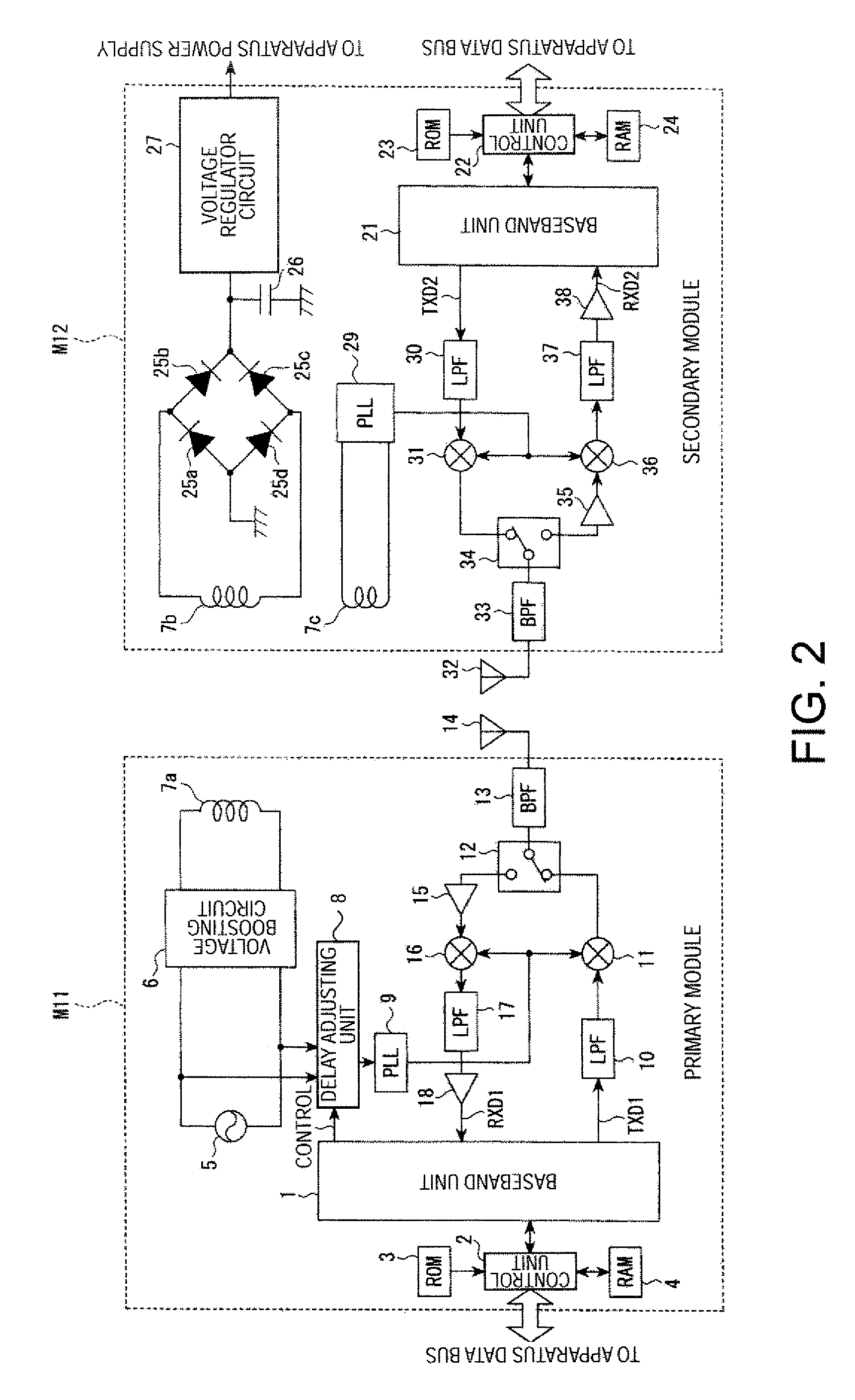
[0047]FIG. 2 is a block diagram showing the schematic configuration of a wireless communication apparatus according to the invention.

[0048] Referring to FIG. 2, in the secondary module M2, instead of the voltage dropping circuit 28 of FIG. 1, a tertiary coil 7c that is electromagnetically coupled to the secondary coil 7b is provided.

[0049] A voltage (clock) induced on the tertiary coil 7c is supplied to the PLL circuit 29, and the PLL circuit 29 can multiply the frequency component of the power carrier wave clock induced on the tertiary coil 7c and output the power carrier wave to the mixers 31 and 36.

[0050] Accordingly, it is unnecessary to provide the voltage dropping circuit 28 of FIG. 1, and thus the circuit configuration is simplified. In additions the frequency component of the power carrier wave clock can be efficiently extracted.

[0051] The above-described wireless communication apparatus can be applied, for example, to a cellular phone, a video camera, a PDA (Personal Dig...

fourth embodiment

[0067]FIG. 4 is an external view showing the system configuration to which a wireless communication apparatus according to the invention is applied.

[0068] In FIG. 4, it is assumed that the secondary module M2 of FIG. 1 is mounted on a digital camera 51, and the primary module M1 of FIG. 1 is mounted on a charging stand 52. Then, alternating current power is supplied to the charging stand 52 through an AC adaptor 54, and the charging stand 52 is connected to a personal computer 53 through a wired cable 55 based on a USB standard or the like.

[0069] The charging stand 52 can charge the digital camera 51 through non-contact power transmission and perform wireless data communication with the digital camera 51. Then, the charging stand 52 can transfer digital data to the personal computer 53.

[0070] The connection of the charging stand 52 and the personal computer 53 may be made using wireless connections in addition to the wired cable 55. Further, in the embodiment of FIG. 4, the descri...


PUM


Abstract

An apparatus includes a wireless transmitter modulating a carrier wave by transmission data and wirelessly communicating a signal, a wireless receiver mixing the wireless transmitter signal and a carrier wave and receiving the transmission data, a power carrier wave clock generator provided on one of the wireless transmitter and receiver generating a power carrier wave clock, a non-contact power transmitter transmitting power between the wireless transmitter and receiver through electromagnetic induction from the power carrier wave clock, a carrier wave generator mounted on the one of the wireless transmitter or receiver, and generating a carrier wave based on the power carrier wave clock, and a carrier wave reproducer mounted on the other of the wireless transmitter or receiver, and reproducing a carrier wave having the same frequency as the carrier wave based on a clock having the same frequency as the power carrier wave clock.

Description

BACKGROUND [0001] 1. Technical Field [0002] The present invention relates to a wireless communication apparatus, and in particular, to one that is suitably applied to a method of transmitting a reference clock used for wireless data communication in a non-contact manner, together with power. [0003] 2. Related Art [0004] As a method that transmits power to an information terminal apparatus, such as a cellular phone, for the sake of charging, there is a method that transmits power using electromagnetic induction in a non-contact manner, in addition to a method that transmits power through a metal contact, such as a connector. The method that transmits power in a non-contact manner can have no poor contact by abrasion or stain and can maintain a waterproof property of a case, compared with the method that transmits power through the metal contact. [0005] In JP-A-9-103037, there is disclosed a method that transfers power control information through an electromagnetic induction coil for ...

Claims


Application Information

Patent Timeline
Patent Type & Authority Applications(United States)
IPC IPC(8): H04M1/00H02J50/00H02J50/10H04B1/40H04B5/02
CPCH04B1/406H04M1/0277H04M1/0214
Inventor IIDA, IZUMI
Owner 138 EAST LCD ADVANCEMENTS LTD
Why Eureka
Try Eureka