Flash pyrolosis method for carbonaceous materials

a carbonaceous material and flash pyrolysis technology, applied in the direction of combustible gas production, thermal non-catalytic cracking, discharging devices, etc., can solve the problem of limited resid conversion in thermal cracker and delayed coker unit operations, the coke product is much more difficult to grind and burn than the delayed coke product, and achieves rapid cooling of the reaction products of the lower boiling poin

Inactive Publication Date: 2007-11-29
BOC GRP INC
View PDF11 Cites 72 Cited by
  • Summary
  • Abstract
  • Description
  • Claims
  • Application Information

AI Technical Summary

Benefits of technology

[0012]This invention utilizes hot supersonic jets with appropriate shape, mechanical energy, and thermal energy to achieve the rapid heating rate indicated on FIG. 2. In order to ensure efficient transfer of the mechanical energy from the hot, high velocity jet to the oil feed, this invention uses an annular hot, high velocity jet that completely surrounds the cylindrical oil feed stream. This large mechanical energy input dramatically increases the surface area for mass and energy transfer and increases the oil temperature by the conversion of mechanical energy to thermal energy. As a result, one can achieve rapid oil heating rates, with minimum localized overheating, by using a hot, high velocity jet at the desired reaction temperature with sufficient mechanical energy to heat the oil feed to the desired reaction temperature. The predominately gaseous flash pyrolysis reactor products can be very quickly cooled using atomized quench oil with a moderate boiling point.
[0017]d) provide sufficient residence time to achieve the desired conversion of the carbonaceous feed material to lower boiling point material; and

Problems solved by technology

During the production of phosgene, a CH4 concentration in the CO of more than 100 ppm is detrimental to the overall process from a standpoint of purity, recovery and environmental emissions.
However, the maximum temperature and minimum residence time of this process was limited to 525° C. and three minutes by the maximum heat flux that can be achieved with fired heater.
As a result, resid conversion in thermal cracker and delayed coker unit operations are typically limited by the maximum temperature and heat flux that can be achieved in a fired heater.
However, one disadvantage of the fluidized bed coker is the coke product is much more difficult to grind and burn than the delayed coke product.
However, this benefit would require much more rapid heating and cooling rates than can be achieved using conventional means.
Clearly, both very high heating rates and cooling rates are required.
Unfortunately, earlier processes only provide methods to achieve very high heating rates or cooling rates, but not both.
However, the large thermal mass of the hot solids makes rapid quenching of the reactants impractical.
Therefore, fluidized bed cokers and catalytic crackers can not achieve the cooling rates indicated in FIG. 2.
Unfortunately, the coke formation rate in the thermal cracking heating coils can only be controlled by limiting the heating rate to rates that are much lower than the heating rates indicated on FIG. 2.

Method used


Image

  • Flash pyrolosis method for carbonaceous materials
  • Flash pyrolosis method for carbonaceous materials
  • Flash pyrolosis method for carbonaceous materials

Examples


example

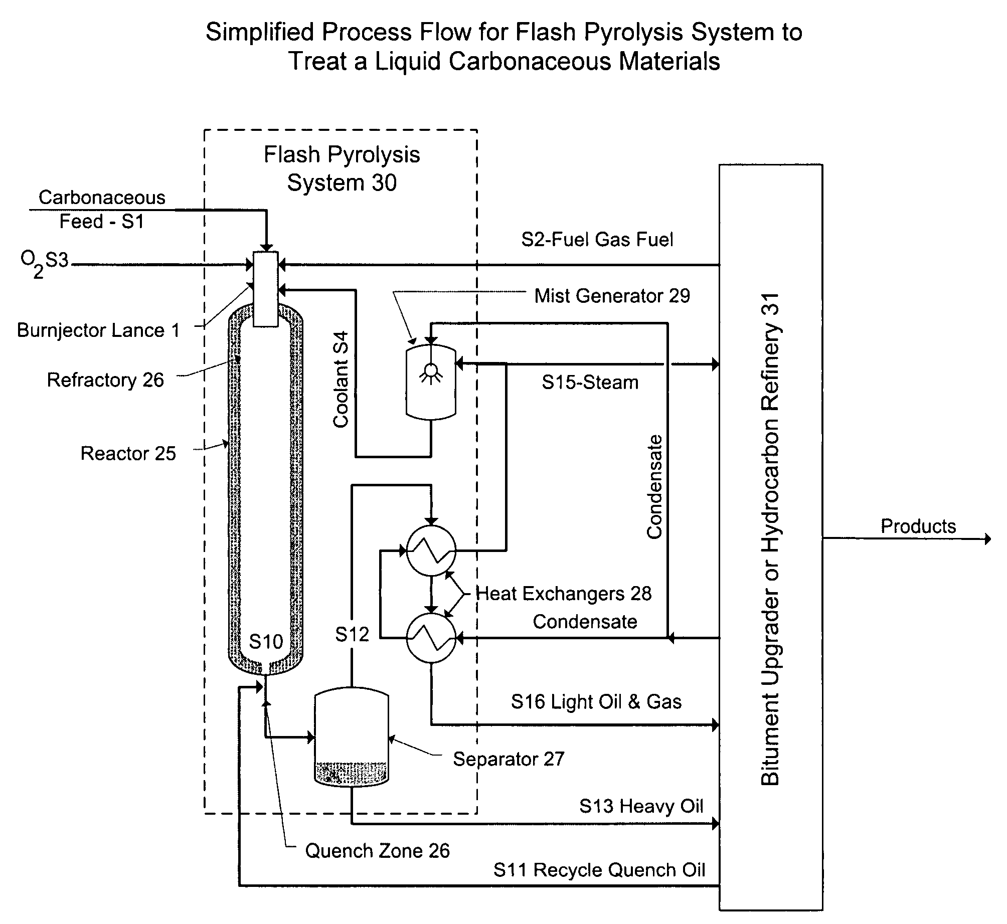
[0049]Table 1 summarizes the vacuum bitumen resid feed properties. Table 2 presented below shows a component material balance for flash pyrolysis system treating 10,000 barrels per day of the bitumen in Table 2.

TABLE 2Example Component Heat & Material BalanceStream12345678910T, ° C.315350252153,2922751,8781,171315710P, bar20.020.020.021.020.00.220.02.02.02.0PhaseLiquidGasGasGas-LiquidGasGas-LiquidGasGasLiquidGasEnergy, MJ / hr1Thermal52,036−6,2890−388,512−6,289−385,277−394,801−477,79752,036−342,977Kinetic———————82,996—212Specie, Kg / hrCH4—6,961.4————————CO————644.2—1,484.9———CO2————18,084.8—16,763.919,096.9—19,096.9H————52.4—0.3———H2————225.5—59.5166.6—166.6H2O(l)———0.0——————H2O(v)———29,779.811,741.129,779.844,880.043,925.2—43,925.2HO————2,660.9—0.1———O2——26,447.5———————Cut 131,865.4———————31,865.41,851.1Cut 237,067.2———————37,067.28,672.2Cut 32,872.2———————2,872.230,238.6Cut 4—————————31,042.9Total71,804.86,961.426,447.529,779.833,408.929,779.863,188.763,188.771,804.8134,993.51Cut 1 a...


PUM

PropertyMeasurementUnit
boiling pointaaaaaaaaaa
temperatureaaaaaaaaaa
velocityaaaaaaaaaa

Abstract

Methods are disclosed for pyrolizing carbonaceous materials to carbonaceous materials having lower boiling points by heating the carbonaceous material to a desired reaction temperature and holding the carbonaceous material in contact with the heat for a sufficient time to achieve the desired reaction to a lower boiling point carbonaceous materials, then rapidly cooling the desired reaction products. The heating source is a jet which will provide hot and high velocity gas streams to the carbonaceous material to be heated.

Description

CROSS REFERENCE TO RELATED APPLICATIONS[0001]This application claims priority from U.S. Provisional Patent Application Ser. No. 60 / 808,647 filed May 26, 2006.BACKGROUND OF THE INVENTION[0002]This invention relates to the purification of streams containing carbon monoxide and more particularly to the removal of low molecular weight hydrocarbons (e.g., methane) from a carbon monoxide stream by adsorption at cryogenic temperatures.[0003]Carbon monoxide (CO) is a major building block for the chemical industry. Besides use as an intermediate in the production of acetic acid, formic acid, and dimethyl formamide to name a few, CO is also a key raw material in the production of phosgene. Phosgene is a key intermediate in many chemical industries, namely polycarbonates, polyurethanes, agricultural chemicals and fine chemicals (pharmaceutical). During the production of phosgene, a CH4 concentration in the CO of more than 100 ppm is detrimental to the overall process from a standpoint of purit...

Claims


Application Information

Patent Timeline
Patent Type & Authority Applications(United States)
IPC IPC(8): C10B49/02
CPCC10B49/02C10G9/36C10J3/62C10J2300/1696C10J2300/093C10J2300/094C10J2300/0959C10J3/66
Inventor SATCHELL, DONALD P.
Owner BOC GRP INC
Why Eureka
Try Eureka