Lanthanide (III) - Doped Nanoparticles And Their Applications

a technology of doped nanoparticles and lanthanide, which is applied in the field of lanthanidedoped nanoparticles, can solve the problems of high integration costs of optical components that can even exceed the fabrication costs of components themselves, low-loss windows, and high cost of glass fibre technology, and achieve the effect of reducing quenching

Inactive Publication Date: 2007-11-29
UNIV OF VICTORIA INNOVATION & DEVMENT
View PDF4 Cites 16 Cited by
  • Summary
  • Abstract
  • Description
  • Claims
  • Application Information

AI Technical Summary

Benefits of technology

[0013] In one aspect of the invention, organic stabilizing layer is suitably selected for reducing quenching.

Problems solved by technology

For optical glass fiber technology the high costs of integration of the optical components can even exceed the fabrication costs of the components itself.
This has disadvantages especially in short range telecommunication where the optical signals have to be processed in a number of optical components.
However, there is a low-loss window.
Such complexity of optical componentry causes glass fibre technology to be expensive.
A disadvantage in the (polymer-based) integrated wavelength structure is that they have relatively high optical losses.
The prior art has shown that organic polymers have a clear potential as low-cost devices, but (intrinsic and extrinsic) optical losses are still relatively high.
Difficulties in doping most likely arise from the large difference in size between the host cation and the lanthanide ion, the charge mismatch between the cations, and the low affinity of lanthanide ions towards sulfur and selenium.
Problems arise when lanthanide ions are used as the active material in polymer-based optical amplifiers.
Reducing the amount of organic bonds in close proximity to the lanthanide ion has improved the luminescence a little bit, but still quenching is a major constraint to the approach.

Method used


Image

  • Lanthanide (III) - Doped Nanoparticles And Their Applications
  • Lanthanide (III) - Doped Nanoparticles And Their Applications
  • Lanthanide (III) - Doped Nanoparticles And Their Applications

Examples


example 1

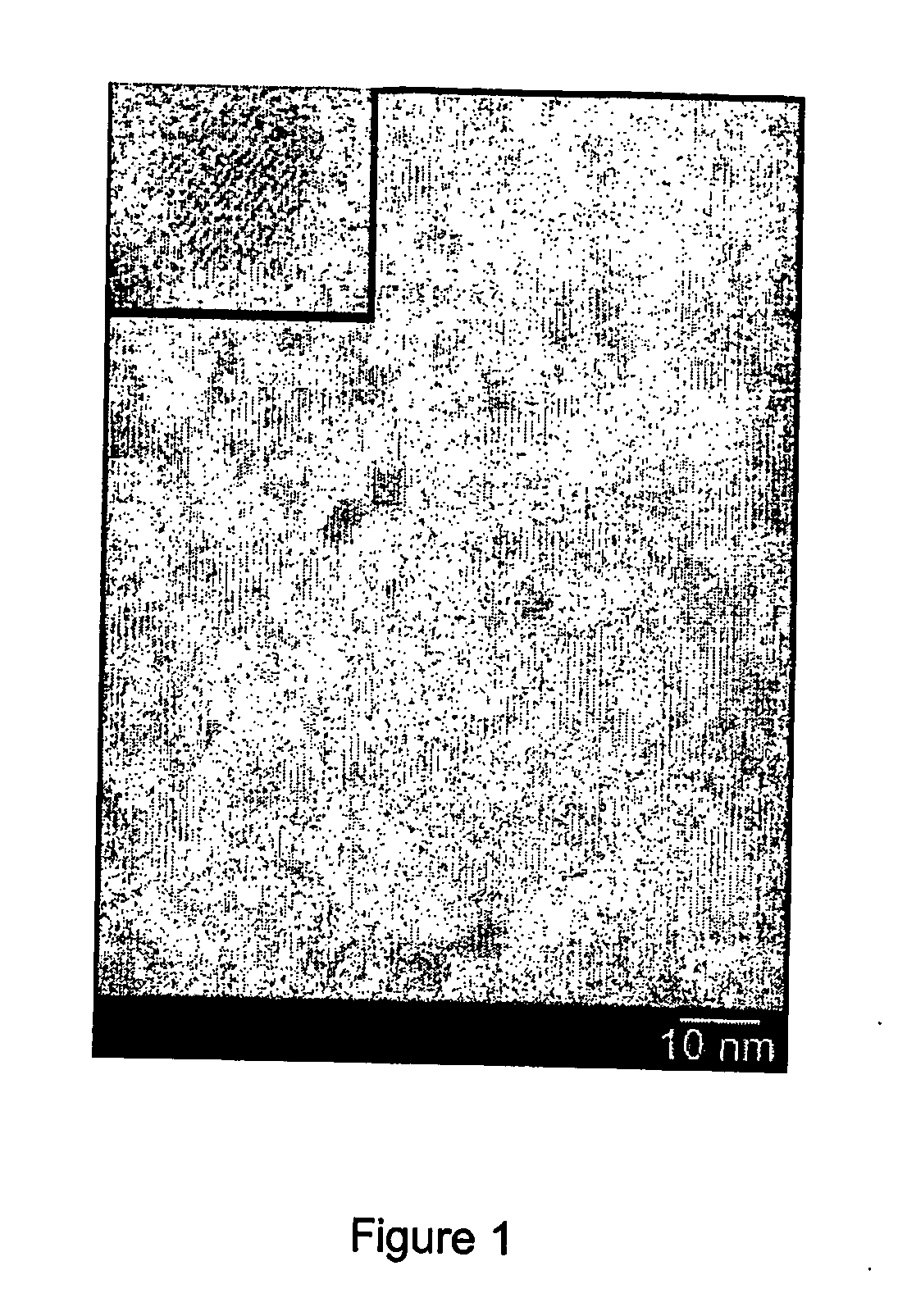
[0136] Characterization of Eu3+ doped nanoparticles. The nanoparticles of TiO2:Eu were characterized by TEM, by evaporating a drop of a nanoparticle solution on a carbon coated copper grid. A typical picture of nanoparticles obtained by heating the reaction mixture for 30 min is shown in FIG. 1. The picture shows small particles with low contrast, due to the small size of the nanoparticles and the low atomic weight of the Ti and O atoms. The nanoparticles were between 3-5 nm in size and in some nanoparticles lattice fringes can be seen, indicating that they are crystalline. The inset shows an enlargement of such a crystalline nanoparticle in which the lattice planes are more clearly observed. The size of the nanoparticles was similar to the sizes found for un-doped TiO2 nanoparticles synthesized using the same method.

[0137] The composition of the nanoparticles was measured using X-ray fluorescence (XRF). For a sample synthesized with a molar ratio of Eu3+ to Ti4+ of 1:17.7 and a re...

example 2

[0145] Quenching in lanthanide doped TiO2 nanoparticles. The quenching routes of the lanthanide ion in the TiO2 nanoparticles were investigated to explain the low quantum yield. Residual OH groups at the surface of the nanoparticles or in the core of the nanoparticles can quench the luminescence of the lanthanide ion. An FT-IR spectrum was measured to see if water or OH groups are present in the product (FIG. 4). The nanoparticles were dried over P2O5 to remove any physisorbed water present on the nanoparticles surface after the synthesis.

[0146] A broad band centered at 3300 cm−1 was found, which can be ascribed to the OH stretching vibration. The peaks at 2925 cm−1 and 2850 cm−1 are due to stretching vibrations of the CH bonds of the TOPO ligand, together with the PO band around 1046 cm−1. The band around 500 cm−1 is caused by TiO bonds in the TiO2 host. To investigate the effect of quenching by OH impurities, the nanoparticles were also synthesized by using deuterated solvents. N...

example 3

[0148] Lanthanide ions emitting in the Near Infrared. Other lanthanide ions were also successfully doped in the TiO2 nanoparticles. The emission and excitation spectra of TiO2 nanoparticles doped with the NIR emitting lanthanide ions Nd3+, Er3+, and Yb3+ are shown in FIG. 6.

[0149] After excitation above the TiO2 band gap, the emission spectra show the typical luminescence of these lanthanide ions. The Nd3+ ion emits at 880, 1060, and 1330 nm originating from the 4F3 / 2→4IJ (J=9 / 2, 11 / 2, 13 / 2) transitions, respectively. The Er3+ ion emits at 1530 nm from the 4I13 / 2→4I15 / 2 transition and the Yb3+ ion at 980 nm from the 2F5 / 2→2F7 / 2 transition. The excitation spectra show the same broad band starting at 350 nm the same as for the TiO2:Eu3+ particles proving that sensitized emission of these ions also occurs. At high particle concentrations of 50 mg / ml, the excitation spectra also show the direct excitation of Er3+ and Nd3+, because the lanthanide absorption lines become visible in the e...


PUM

PropertyMeasurementUnit
telecommunication wavelengthsaaaaaaaaaa
pump poweraaaaaaaaaa

Abstract

A photonic material comprising a core and an envelope is provided for use in telecommunications, diagnostics, imaging and other applications. In its simplest form, the core comprises at least one nanoparticle. The nanoparticle comprises an inorganic material and at least one luminescent ion, wherein the inorganic material is suitably selected to bind the luminescent ion. The envelope comprises a suitably selected organic stabilizing layer that overlays the core. The core and envelope may have a shell located between them.

Description

FIELD OF THE INVENTION [0001] The present invention relates to lanthanide-doped nanoparticles, their synthesis and use thereof. More specifically, the invention relates to lanthanide-doped nanoparticles having superior optical properties, including reduced quenching, effective excitation and a broad bandwidth. BACKGROUND OF THE INVENTION [0002] Lanthanide ions are widely used as the active luminescent material in optical amplifiers and lasers. The major advantages of the lanthanide ions are the long luminescence lifetime and the high quantum efficiency that can be achieved at the major telecommunication wavelengths of 1300 and 1530 nm. The ions are extremely stable under laser action because the optical transitions involve electronic transitions within the ion itself. No chemical bonds are involved so degradation does not occur. The long luminescence lifetime of the lanthanide ions makes laser action relatively easy to achieve with cheap pump sources. [0003] The luminescence of the ...

Claims


Application Information

Patent Timeline
Patent Type & Authority Applications(United States)
IPC IPC(8): G02B6/02G02B6/00C09K11/77
CPCC09K11/77G06F1/3203Y10T428/2993Y10T428/2991Y10T428/2998Y10T428/2995
Inventor VAN VEGGEL, FRANCISCUS CORNELIUS JACOBUS MARIASTOUWDAM, JAN WILLEM
Owner UNIV OF VICTORIA INNOVATION & DEVMENT
Why Eureka
Try Eureka