Electrochromic Device with Self-forming Ion transfer Layer and Lithium Fluoro-Nitride Electrolyte

a technology of lithium fluoro-nitride and self-forming ion transfer layer, which is applied in the field of multi-layer structure and fabrication techniques of forming electrical devices, can solve the problems of imposing limitations on the switching speed and color uniformity, and achieve the effect of improving the uniformity of coloration and the switching speed

Active Publication Date: 2007-12-20
ECLIPSE ENERGY SYST
View PDF8 Cites 70 Cited by
  • Summary
  • Abstract
  • Description
  • Claims
  • Application Information

AI Technical Summary

Benefits of technology

[0012]Another aspect of the invention is that it provides a method of making an electrochromic device by sequentially forming a plurality of layers of selected materials in a vacuum processing chamber. An initial step may comprise depositing a first electrode layer on a substrate and then venting the vacuum processing chamber so that bus bar masking can be applied to the first electrode layer. Subsequently, the processing chamber is re-evacuated and a precursor film used for forming an electrochromic film is deposited on the first electrode layer. This precursor layer may comprise tungsten oxide evaporated from a tungsten oxide source. A source of ionized nitrogen is then provided adjacent the substrate and lithium is deposited in the presence of the ionized nitrogen to both form a thin lithium-nitride ion transfer film on the exposed surface and to diffuse lithium into the precursor film to thereby form the electrochromic layer. An electrolyte film comprising lithium is then deposited onto the ion transfer film, an ion storage film is deposited onto the electrolyte film and a second, transparent, electrode film is deposited onto the ion storage film. The vacuum processing chamber is then vented and contacts are selectively applied to portions of the second electrode film Finally, an overcoat layer, which is preferably a transparent polymer, is applied over the second electrode so as to provide environmental protection for the ECD.
[0013]In a preferred process making the ECD requires that the vacuum processing chamber be pumped down only twice. The first evacuation is used to deposit a first electrode that will subsequently contact the EC layer. During the second evacuation all the other thin film portions of the ECD—i.e., the EC, ion transfer, EL, IS and IS-electrode layers—are formed. It is thus one of the objects of the invention to provide an ECD fabrication process that is faster than those used in the prior art and that require fewer vacuum processing cycles.
[0016]Preferred processes of the invention lead to a reduction in overall process time when compared to prior art processes for making electrochromic devices. This advantage may be gained by a design that avoids the use of thick, slowly deposited flexibility and adhesion promoting layers and that does not require venting of the vacuum processing chamber prior to deposition of the IS electrode.

Problems solved by technology

The electronic conductivity of these layers is often an important consideration and can impose limitations on the switching speed and the uniformity of coloration.

Method used


Image

  • Electrochromic Device with Self-forming Ion transfer Layer and Lithium Fluoro-Nitride Electrolyte
  • Electrochromic Device with Self-forming Ion transfer Layer and Lithium Fluoro-Nitride Electrolyte
  • Electrochromic Device with Self-forming Ion transfer Layer and Lithium Fluoro-Nitride Electrolyte

Examples


example 1

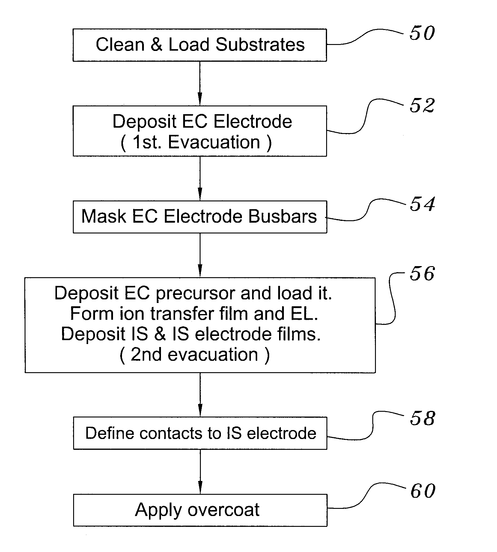
A Preferred Structure was Made by the Process Depicted in Overview in FIG. 3.

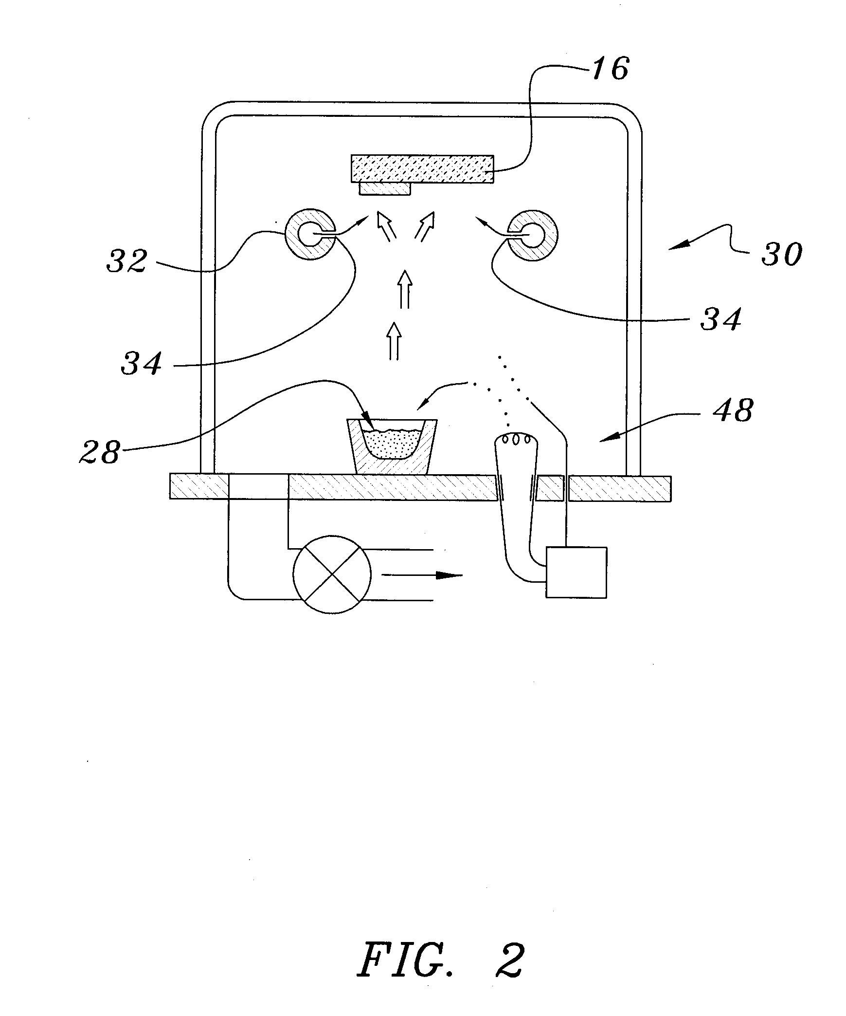
[0039]Both glass and polyethylene terephthalate substrates 16 were cleaned with detergent and deionized water, spun dry under clean room conditions, and loaded (Step 50) into a vacuum processing chamber 30. The chamber 30 was then pumped down to a background pressure of approximately 10−5 Torr. Indium-tin-oxide was deposited from a source 28 heated by an electron beam 48 at a rate of approximately 0.2 nm / sec to yield a total thickness of 200 nm (Step 52). The vacuum system was then opened and bus bar metallization patterns were applied to the ITO layer (Step 54).

[0040]The samples were re-loaded into the vacuum chamber, which was evacuated to 10−7 Torr in a second evacuation (Step 56). About 300 nm of tungsten trioxide was deposited by e-beam evaporation at a rate of about 1 nm / sec. A ‘nitrogen shower’ was then turned on to provide ionized nitrogen at a pressure of about 5×10⁻⁵ Torr near the substrate. Lithi...

example 2

Effect of Using Ionized Nitrogen During Lithium Loading

[0047]In two experimental runs, ECDs were made in accordance with the process spelled out in Example 1, except that ionized nitrogen was not used during lithium evaporation and loading. In one of these runs nitrogen was introduced at the same background pressure as noted above, but the ionizing field was not applied. In the other run, no nitrogen was introduced into the processing chamber. In both cases, the ECDs operated, but the switching speeds were four to five times slower than for the preferred devices.

example 3

Effect of Using Ionized Nitrogen During Electrolyte Layer Formation

[0048]In two experimental runs, ECDs were made in accordance with the process spelled out in Example 1, except that ionized nitrogen was not used during lithium fluoride evaporation. In one of these runs nitrogen was introduced at the same background pressure as noted above, but the ionizing field was not applied. In the other run, no nitrogen was introduced into the processing chamber. In both cases, the ECDs operated, but the switching speeds were one hundred to one hundred fifty times slower than for the preferred devices.


PUM

PropertyMeasurementUnit
thicknessaaaaaaaaaa
thickaaaaaaaaaa
thickaaaaaaaaaa

Abstract

A method of preparing an electrochromic device involves forming multiple layers of selected materials on a substrate in a vacuum processing chamber. A first of these layers is an electrode layer deposited directly on the substrate and used for making contact to a subsequently deposited precursor film, preferably tungsten oxide, from which an electrochromic layer is formed by lithium loading in the presence of ionized nitrogen. This not only forms the electrochromic layer by diffusion of the lithium into the tungsten oxide, but also forms a thin lithium nitride ion transfer layer on the then exposed surface. Subsequently, a lithium fluoro-nitride electrolyte layer is formed on the ion transfer layer by evaporation from a lithium fluoride source in the presence of ionized nitrogen. An ion storage layer, which may be a vanadium oxide and a transparent second electrode layer are subsequently vacuum deposited.

Description

CROSS REFERENCE TO OTHER APPLICATIONS[0001]This application is a divisional of applicant's U.S. Ser. No. 11 / 425,379, filed Jun. 20, 2006.BACKGROUND OF THE INVENTION[0002]1. Field of the Invention[0003]The invention relates to particular multi-layer structure and fabrication techniques for forming electrical devices, and in particular, for forming electrochromic devices of the sort used to modulate visible illumination.[0004]2. Background Information[0005]Generally speaking, an electrochromic device (‘ECD’) comprises two active layers separated by an electrolyte (sometimes referred to as an ‘EL’ or ‘EL layer’) through which a selected mobile ion can be controllably moved from one of the active layers to the other. Both of the active layers can contain varying concentrations of the mobile ion. In at least one of the active layers, commonly referred to as the ‘electrochromic layer’ (‘EC layer’), changes in the ion concentration are accompanied by changes in the color and transparency o...

Claims


Application Information

Patent Timeline
Patent Type & Authority Applications(United States)
IPC IPC(8): B05D5/12G02F1/1524
CPCG02F1/1523G02F1/1524
Inventor DEMIRYONT, HULYA
Owner ECLIPSE ENERGY SYST
Why Eureka
Try Eureka