
Picture Processing Engine and Picture Processing System

a picture processing engine and picture processing technology, applied in the field of picture processing engines and picture processing systems, can solve the problems of increasing power consumption, increasing power consumption, and relatively high power consumption of memory, and achieve the effects of reducing the total capacity of instruction memory, reducing the number of instructions, and reducing the power consumed in reading instruction memory

Inactive Publication Date: 2007-12-20
RENESAS ELECTRONICS CORP
View PDF9 Cites 10 Cited by
  • Summary
  • Abstract
  • Description
  • Claims
  • Application Information

AI Technical Summary

Benefits of technology

[0010]JP-A-2000-57111 discloses a SIMD type ALU. A general image processing is an algorithm for executing the same calculation to the whole two-dimensional block. In achieving this by means of a SIMD type ALU, the same instruction is supplied every cycle, in which only the read register number and write register number of a general-purpose register vary. This means that an instruction fetch is carried out every cycle, and thus a memory in which the instruction is stored should be accessed every cycle. The rate of power which the memory consumes is relatively high relative to the entire power consumption of the LSI. Accordingly, reading an instruction memory every cycle increases the power consumption.
[0011]Moreover, the SIMD type ALU is configured to carry out calculation to the limited input data. For example, in carrying out a vertical convolution calculation or the like, the calculation of each element is carried out by a plurality of instruction sequences and finally each calculation result is added. If a carry is taken into consideration, the processing cycles of a bit extension as a pre-processing, a rounding processing as a post-processing, and the like, will increase as compared with the processing cycle of the actual convolution calculation. Accordingly, a high operation frequency is required and thus the power consumption will increase.
[0013]JP-A-2001-100977 discloses a VLIW type CPU. According to this method, as the number of arithmetic logical units to be operated in parallel is increased, the number of instructions to read in one cycle also increases and thus the power consumption is high. Moreover, in proportion to the number of arithmetic logical units, the number of register ports increases and the area cost is high and thus this also increases the power consumption.
[0014]Then, the present invention is intended to provide a technique to reduce power consumption in carrying out image processing by means of processors.
[0017]With such configuration, a power consumed in reading an instruction memory is reduced by reducing the access frequency to the instruction memory, for example. Moreover, by reducing the number of instructions and sharing an instruction memory, a total capacity of the instruction memory is reduced, thus reducing the number of transistors to be charged and discharged and achieving low power consumption.

Problems solved by technology

The rate of power which the memory consumes is relatively high relative to the entire power consumption of the LSI.
Accordingly, reading an instruction memory every cycle increases the power consumption.
Accordingly, a high operation frequency is required and thus the power consumption will increase.
Accordingly, when processes are active in a plurality of processors simultaneously, a conflict of the instruction memory accesses will occur and thus the operation rate of the processors will substantially decrease to cause a performance decrease.
According to this method, as the number of arithmetic logical units to be operated in parallel is increased, the number of instructions to read in one cycle also increases and thus the power consumption is high.
Moreover, in proportion to the number of arithmetic logical units, the number of register ports increases and the area cost is high and thus this also increases the power consumption.

Method used


Image

  • Picture Processing Engine and Picture Processing System
  • Picture Processing Engine and Picture Processing System
  • Picture Processing Engine and Picture Processing System

Examples


embodiment 1

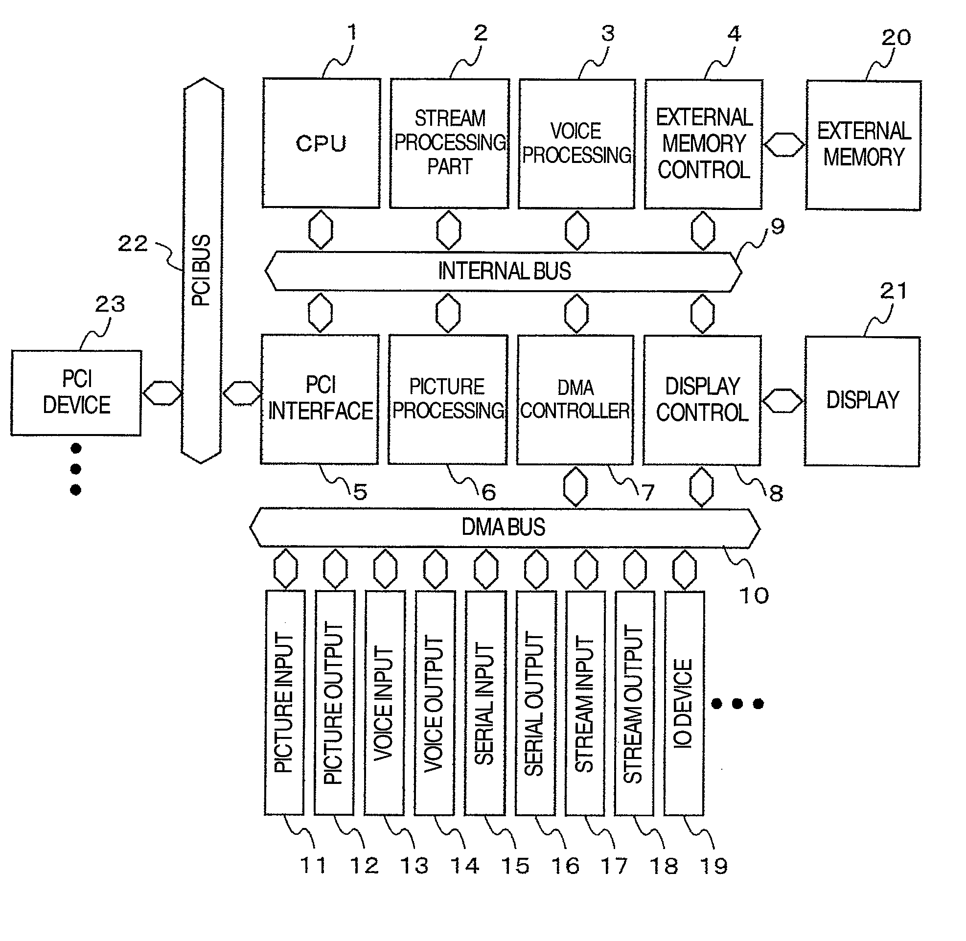
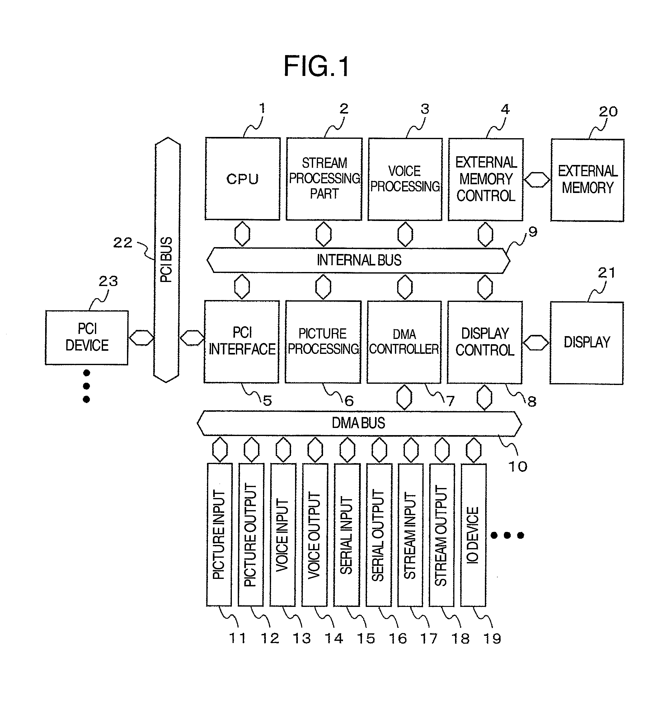
[0045]A first embodiment of the present invention will be described in detail with reference to the accompanying drawings. FIG. 1 is a block diagram of an embedded system in this embodiment. In this embedded system, CPU 1 for carrying out a control of the system and a general processing, a stream processing part 2 for carrying out a stream processing, which is one of the processings of a video codec, such as MPEG, a picture processing part 6 which carries out encoding and decoding of the video codec in combination with the stream processing part 2, a voice processing part 3 for carrying out encoding and decoding of a voice codec, such as AAC and MP-3, an external memory control part 4 which controls an access to an external memory 20 consisting of SDRAM and the like, a PCI interface 5 for connecting to a PCI bus 22 which is a standard bus, a display control part 8 for controlling an image display, and a DMA controller 7 which carries out direct memory access to various IO devices, a...

embodiment 2

[0099]A second embodiment of the present invention is described using FIG. 14. FIG. 14 is a block diagram of the picture processing engine 66 in this embodiment. There are three differences from the picture processing engine 66 of the first embodiment shown in FIG. 6. The first one is that the input data 30i and the calculation data 30wb of the CPU part 30 are connected to a vector calculation part 46. The input data 30i is a data to be inputted to the register file 304 in the CPU part 30 and can update the data of the register file 304. The calculation data 30wb is a calculation result of the CPU part 30 and is inputted to the vector calculation part 46. The second one is that an instruction memory control part 47 in place of the instruction memory control part 32 of FIG. 6 is connected. The instruction memory control part 47 has a plurality of program counters and controls the instruction memory 31. In conjunction with this, the third difference is that the vector calculation part...

embodiment 3

[0112]A third embodiment is described using FIG. 20. FIG. 20 shows a configuration of a CPU part arranged in the picture processing engine 66 in this embodiment. In the first embodiment, a configuration of one CPU part 30 was described, and in the second embodiment a configuration of two CPUs consisting of the CPU part 30 and vector calculation part 46 was described. In the third embodiment, two or more CPUs are connected in series and in a ring shape. In FIG. 20, the CPU part 30 capable of accessing to the data memory 35 is arranged in the front CPU, a plurality of vector calculation parts 46 and 46n are connected in series, and at the end terminal a CPU part 30s capable of accessing to the data memory 35 is connected. The calculation data 30i of the CPU part 30s is again connected to an input data part of the CPU part 30. At this time, each CPU includes a program counter, respectively, and actually includes a plurality of program counters in the instruction memory control part 47 ...


PUM


Abstract

To provide a technique to reduce power consumption when carrying out image processing by processors. For the purpose of this, for example, a means for specifying a two-dimensional source register and destination register is provided in an operand of an instruction, and the processor includes a means which executes calculation using a plurality of source registers in a plurality of cycles and obtains a plurality of destinations. Moreover, in an instruction to obtain a destination using a plurality of source registers and consuming a plurality of cycles, a data rounding processing part is connected to a final stage of a pipeline. With such configurations, the power consumed when reading an instruction memory is reduced by reducing the access frequency to the instruction memory, for example.

Description

INCORPORATION BY REFERENCE[0001]The present application claims priority from Japanese application JP2006-170382 filed on Jun. 20, 2006, the content of which is hereby incorporated by reference into this application.BACKGROUND OF THE INVENTION[0002]The present invention is in the technical field of picture processing engines and picture processing systems, and in particular relates to a picture processing engine, in which a CPU and a direct memory access controller are bus connected to each other, and a picture processing system including the same.[0003]As the semiconductor process is refined, techniques called SOC (system on chip) for achieving a large-scale system on one LSI, and SIP (system in package) for mounting a plurality of LSIs in one package are becoming mainstream. Such a large scale integration of logic, as seen in embedded type applications, has allowed totally different functions, such as a CPU core and a video codec accelerator or a large-scale DMAC module, to be moun...

Claims


Application Information

Patent Timeline
IPC IPC(8): G06F9/30
CPCG06F9/30014G06F9/3885G06F9/30087G06F9/30036G06F15/16G06T1/00G06F15/76
Inventor HOSOGI, KOJIEHAMA, MASAKAZUNAKATA, HIROAKIIWATA, KENICHIMOCHIZUKI, SEIJIYUASA, TAKAFUMIKOBAYASHI, YUKIFUMISHIBAYAMA, TETSUYAUEDANOBORI, MASAKI
Owner RENESAS ELECTRONICS CORP
Learn More