Multi-Layer Piezoelectric Element and Method for Manufacturing the Same

a piezoelectric element and multi-layer technology, applied in the direction of machines/engines, generators/motors, mechanical equipment, etc., can solve the problems of contact failure, displacement characteristic deterioration, displacement characteristic alteration during operation, etc., to improve the effect of wedge, bonding strength, and bonding strength

Active Publication Date: 2008-01-10
KYOCERA CORP
View PDF10 Cites 16 Cited by
  • Summary
  • Abstract
  • Description
  • Claims
  • Application Information

AI Technical Summary

Benefits of technology

[0023] The multi-layer piezoelectric element of the present invention having the constitution described above has the cleft having the wedge which contains glass formed in the side face of the stack, and the cleft is filled with the glass that is contained in the external electrode. With this constitution, the glass contained in the wedge and the glass contained in the external electrode join with each other with good affinity thereby increasing the bonding strength between the external electrode and the piezoelectric layer and causing the external electrodes to be bonded firmly onto the side faces of the stack, and therefore such a problem can be prevented from occurring as the external electrodes peel off from the side faces of the stack even when operated over a long period of time under a high electric field.
[0024] In the multi-layer piezoelectric element of the present invention, the effect of the wedge can be improved by joining the cleft with the internal electrode.
[0025] Also in the multi-layer piezoelectric element of the present invention, when the glass contained in the wedge and the glass contained in the external electrode are constituted from the same components, bonding strength between the external electrode and the piezoelectric layer can be increased further and the cleft can be filled with the glass in the same process where the external electrodes are baked, so that the number of manufacturing processes can be reduced.
[0026] When the maximum depth of the cleft in a direction perpendicular to the stacking direction of the stack is 100 μm or less, it becomes easier to fill the cleft with glass, and it is made possible to suppress destruction from developing from the cleft due to stress generated in the piezoelectric layer.
[0027] Reliability of the device can be improved by controlling the maximum width of the cleft within 15 μm.
[0028] It becomes easier to fill the cleft with glass, and it is made possible to suppress destruction from developing from the cleft through continuous operation of the multi-layer piezoelectric element by controlling the filling ratio of glass in the cleft to 70% or more.

Problems solved by technology

The multi-layer piezoelectric actuator of the prior art has such problems that, when operated continuously over a long period of time under a high electric field and a high pressure, contact failure occurs in the junction between the external electrode and the internal electrode, thus shutting off the current supply to part of the piezoelectric layers and resulting in alteration of the displacement characteristic during operation.
However, the external electrode and the internal electrode cannot be bonded together sufficiently simply by applying and baking the electrically conductive paste on the side face of the stack, and the external electrode may peel off the side face of the stack and the end of the internal electrode when operated continuously over a long period of time under a high electric field, thus resulting in contact failure and deterioration in the displacement characteristic.

Method used


Image

  • Multi-Layer Piezoelectric Element and Method for Manufacturing the Same
  • Multi-Layer Piezoelectric Element and Method for Manufacturing the Same
  • Multi-Layer Piezoelectric Element and Method for Manufacturing the Same

Examples


first embodiment

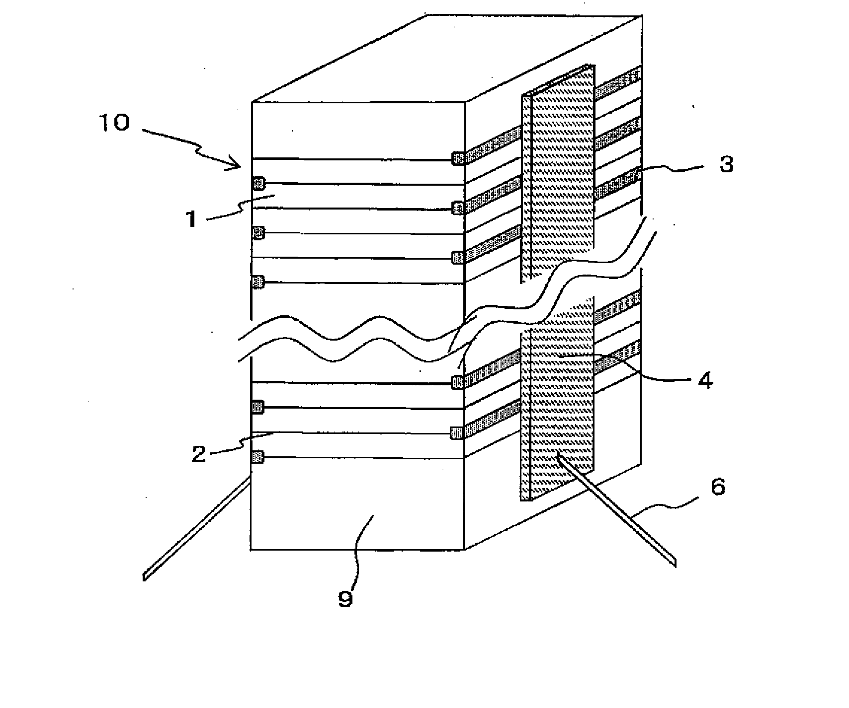
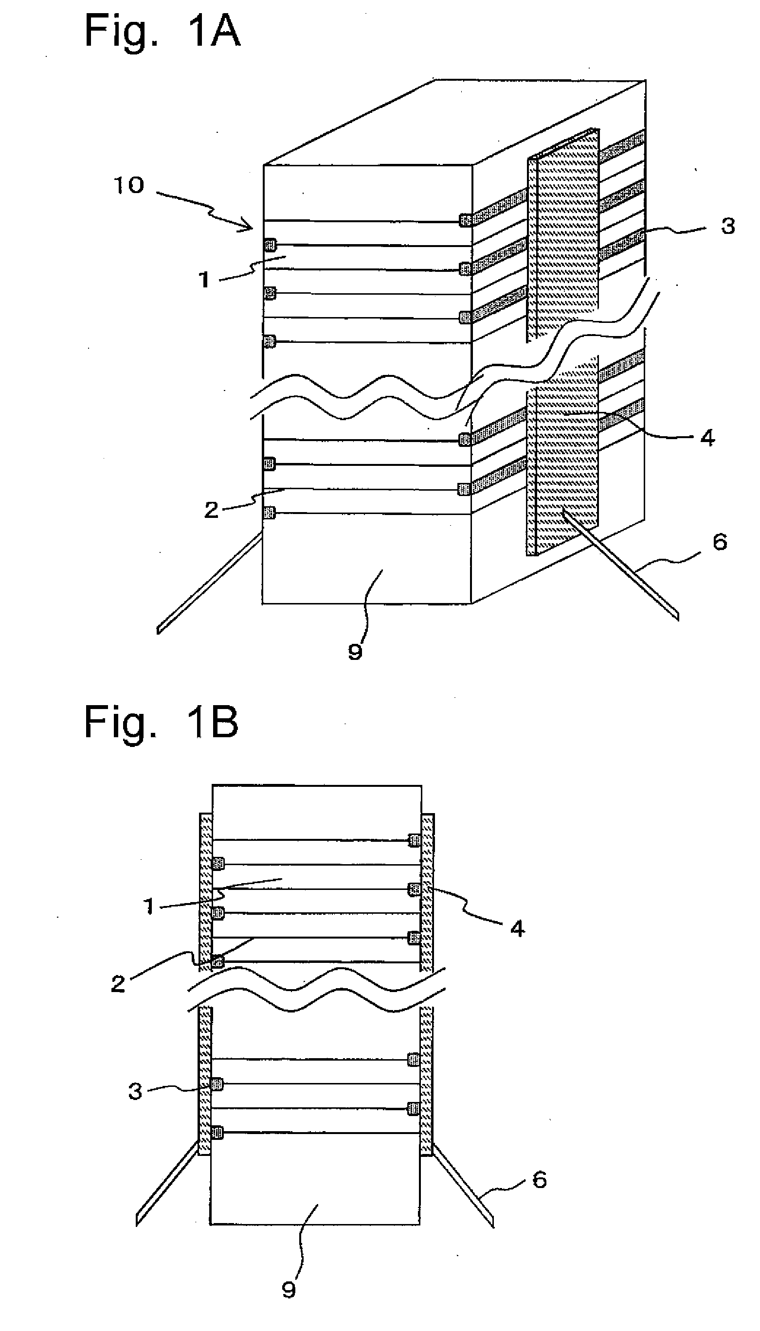
[0070]FIG. 1A and FIG. 1B show the constitution of the multi-layer piezoelectric actuator comprising the multi-layer piezoelectric element according to the first embodiment, FIG. 1A being a perspective view and FIG. 1B being a side view thereof.

[0071] The multi-layer piezoelectric element according to the first embodiment is constituted by forming the external electrodes 4, from an electrically conductive material containing silver as the main component and glass, on the side faces of the stack 10 having a shape of rectangular prism formed by stacking a plurality of piezoelectric layers 1 and a plurality of internal electrodes 2, as shown in FIG. 1A.

[0072] In the first embodiment, the external electrodes 4 are formed so that the end of the internal electrode 2 is covered by an insulating material 3 in every other layer and make electrical connection with the internal electrode 2 which is not covered by the insulating material 3 on the side faces of the stack 10, with a lead wire 6...

second embodiment

[0127] The multi-layer piezoelectric element according to the second embodiment of the present invention is made similarly to the first embodiment, except that the green ceramic stack, made by stacking a plurality of green sheets (green ceramic layers) having the electrically conductive paste printed on the top surface thereof, is subjected to binder removal operation and fired after cutting the stack by a method to be described later.

[0128] The green ceramic stack may be cut by dicing, cutting or water jet, among which water jet is preferably employed since water jet is directed with a high pressure from a small nozzle to an object to be cut, and therefore the process is not affected by heat unlike the dicing process.

[0129] However, in the conventional method of cutting the green ceramic stack by means of water jet, since water jet of high pressure contains abrasive particles made of garnet, there has been such a problem as the garnet particles remain on the cut surface of the gr...

third embodiment

[0151]FIG. 6 shows an injection apparatus according to the third embodiment constituted from the multi-layer piezoelectric element of the present invention, comprising a casing 31 which has an injection hole 33, a piezoelectric actuator 43 housed in the casing 31, and a valve 35 which is driven by the multi-layer piezoelectric actuator to discharge the liquid from the injection hole 33.

[0152] The injection hole 33 is provided with a fuel passage 37 disposed so as to communicate therewith. The fuel passage 37 is connected to a fuel source that is provided outside of the apparatus, so as to receive a fuel supplied thereto at a high pressure that remains always constant. When the needle valve 35 opens the injection hole 33, the fuel that fills the fuel passage 37 is injected at a predetermined level of high pressure into a fuel chamber of an internal combustion engine (not shown).

[0153] The valve 35 has an enlarged top portion where the diameter is made larger, forming a cylinder 39 ...


PUM

PropertyMeasurementUnit
depthaaaaaaaaaa
widthaaaaaaaaaa
particle sizeaaaaaaaaaa

Abstract

A multi-layer piezoelectric element having high durability wherein the internal electrodes and the external electrodes do not break even when operated continuously over a long time under high electric field and high pressure is provided. The multi-layer piezoelectric element comprises a stack formed by stacking at least one piezoelectric layer and internal electrodes consisting of first and second internal electrodes one on another, and external electrodes formed on two side faces of the stack with one of which being connected to the first internal electrode and the other external electrode being connected to the second internal electrode, wherein the external electrodes contain a conductive material and glass, the side whereon the external electrode is formed has cleft which has a wedge which contains glass formed therein, and the cleft is filled with the glass contained in the wedge and glass contained in the external electrode.

Description

TECHNICAL FIELD [0001] The present invention relates to a multi-layer piezoelectric element, a method for manufacturing the same and an injection apparatus, for example, piezoelectric transducer, fuel injection apparatus of automobile engine, and multi-layer piezoelectric actuator used as a drive unit in precision positioning device or vibration preventing device or the like for an optical apparatus. BACKGROUND ART [0002] Multi-layer piezoelectric actuators constituted from piezoelectric layers and internal electrodes stacked alternately one on another have been known as an example of the multi-layer piezoelectric element. The multi-layer piezoelectric actuators can be divided into two categories: fired-at-once type and stacked type that comprises piezoelectric porcelain and internal electrode sheet stacked alternately one on another. When the requirements to reduce the operating voltage and the manufacturing cost are taken into consideration, the multi-layer piezoelectric actuator ...

Claims


Application Information

Patent Timeline
Patent Type & Authority Applications(United States)
IPC IPC(8): H01L41/187H01L41/083H01L41/24F02M51/00F02M51/06F02M63/00H01L41/047H01L41/22H01L41/27H01L41/293H01L41/337H02N2/00
CPCF02M51/0603H01L41/0472H01L41/273Y10T29/42H01L41/338Y10T29/49155H01L41/293H10N30/872H10N30/063H10N30/053H10N30/088
Inventor NAKAMURA, SHIGENOBUMASUYAMA, HIROYUKI
Owner KYOCERA CORP
Why Eureka
Try Eureka