
High-na projection objective

a projection objective and high-na technology, applied in the field of catadioptric projection objectives, can solve the problems of limited supply, high-index materials in optical quality, and the theoretical limit of image-side numerical aperture is normally not reached, so as to reduce the maximum value of lens diameters

Inactive Publication Date: 2008-01-10
CARL ZEISS SMT GMBH
View PDF13 Cites 28 Cited by
  • Summary
  • Abstract
  • Description
  • Claims
  • Application Information

AI Technical Summary

Benefits of technology

[0029] It has been found that providing negative lens groups at different positions within the image-side imaging subsystem and separated by a positive lens group (intermediate positive lens group) with generally con verging effect on the transiting radiation, large contributions to correction of aperture-dependent aberrations, such as spherical aberration and coma, can be provided even with spherical lens surfaces. The effect may be complemented and completed by providing aspheric lens surfaces of appropriate shape at selected positions. Since a framework of suitably curved and distributed spherical lens surfaces may provide a major contribution to correction, relatively small numbers of aspheric lens surfaces may be sufficient to correct residual aberrations.
[0046] In embodiments adapted for using an immersion medium in the image space it has been found useful to provide a last optical element having an edge thickness ETLOE according to ETLOE<NA×10 [mm], where the edge thickness is the thickness of the last optical element at the edge of the optically utilized area measured in the direction of the optical axis. Preferably, ETLOE may be smaller than 14 mm or even smaller than 10 mm. This contributes to an axially compact design. Further, a significant deflection of rays of a beam bundle with a very large opening angle close to the image surface is obtained, thereby reducing the maximum values of lens diameters upstream of the last optical element, particularly between the pupil surface of the image-side imaging subsystem and the image surface.

Problems solved by technology

The theoretical limit for image-side numerical aperture is normally not reached, since the propagation angles between the rays limiting the beam bundle and the optical axis then become very large.
However, high-index materials in an optical quality suitable for this purpose are in limited supply and procedures for reproducably treating such materials during manufacturing are still being developed.
The correction of chromatic aberrations (color correction) is an other problem in systems designed for wavelengths below about 260 nm since the Abbe numbers of those transparent materials that are available lie rather close to one another.
Further, the high prices of the materials involved and limited availability of crystalline calcium fluoride in sizes large enough for fabricating large lenses represent problems.
However, large lens diameters are not desirable due to the limited availability of optical material in sufficient quality and also because the mechanical stability is negatively affected and the optical systems tend to become axially large.
However, since the reflecting surfaces of the concave mirrors are interrupted at the bores, the pupil of the system is obscured.

Method used


Image

  • High-na projection objective
  • High-na projection objective
  • High-na projection objective

Examples


first embodiment

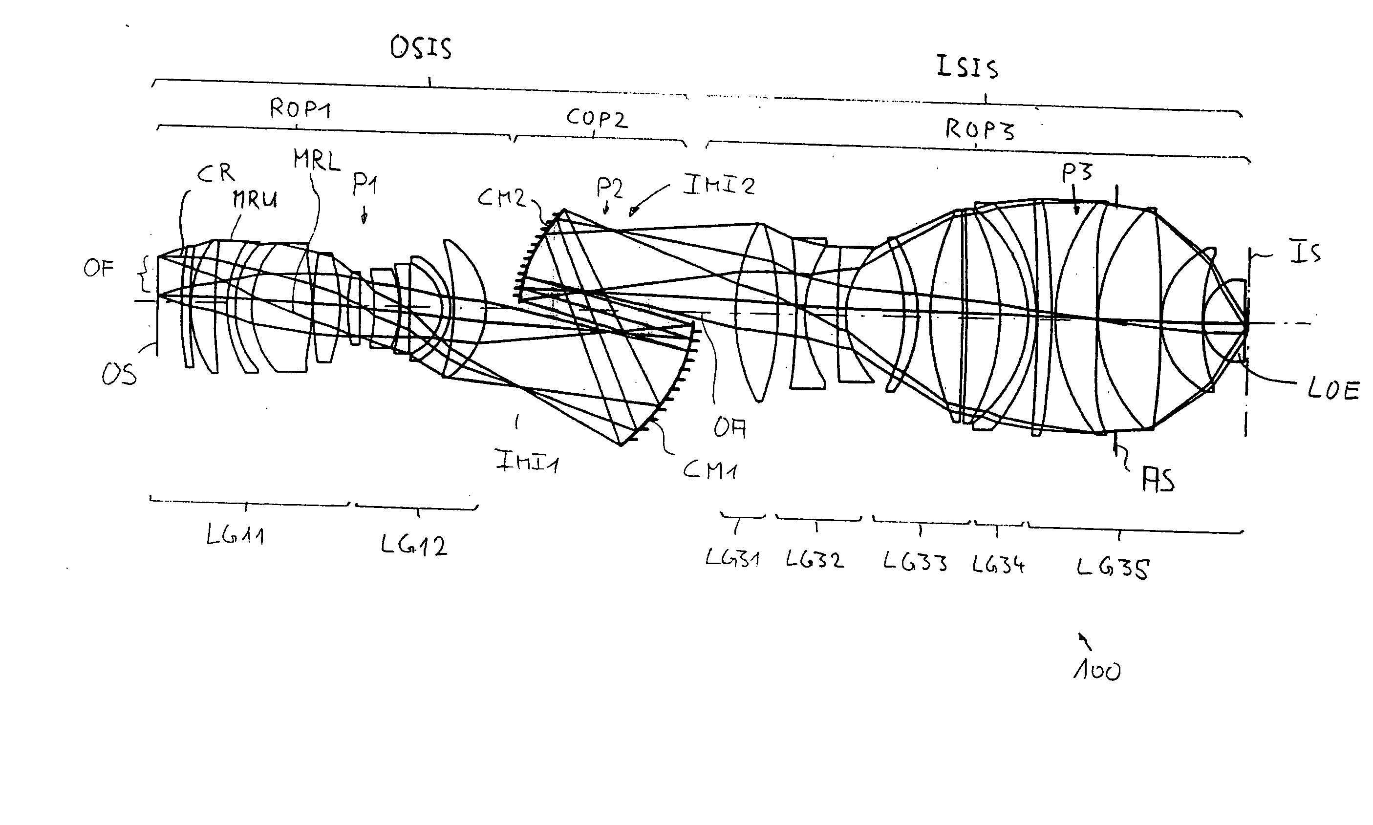
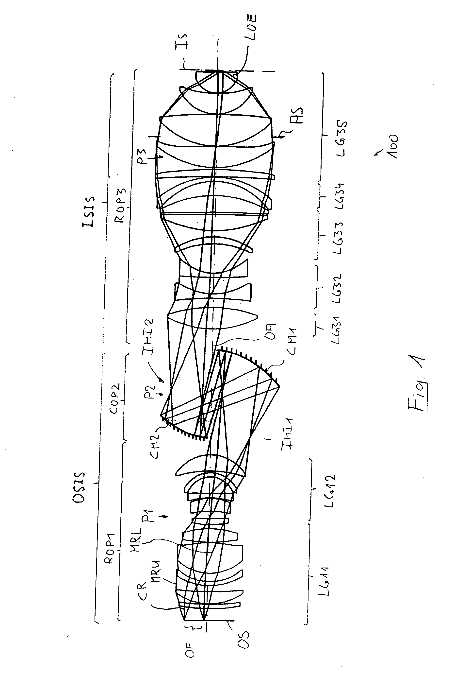
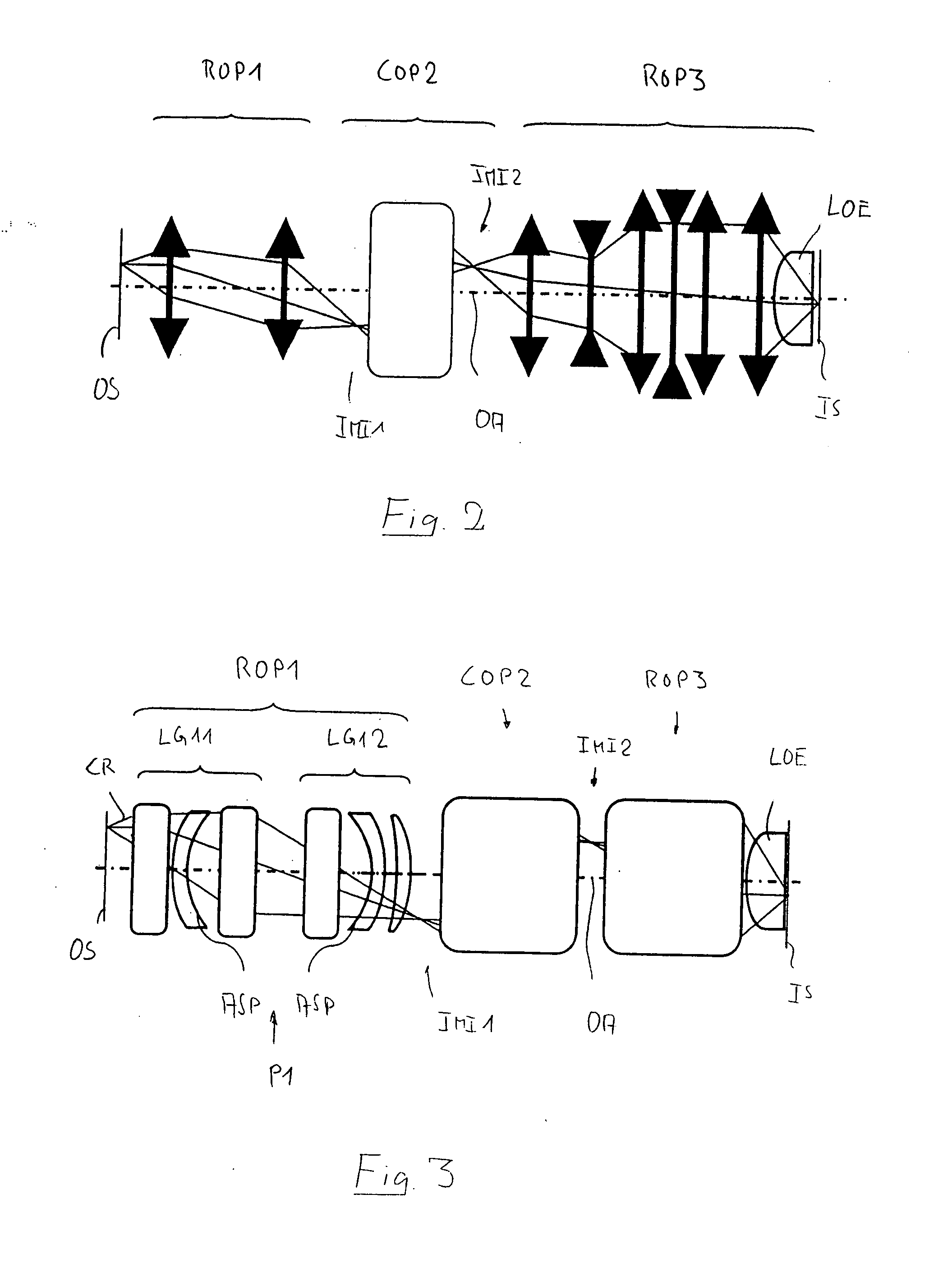
[0063]FIG. 1 shows a catadioptric projection objective 100 according to the invention designed for about 193 nm UV working wavelength. It is designed to project an image of a pattern on a reticle (or mask) arranged in the planar object surface OS into the planar image surface IS on a reduced scale, for example, 4:1, while creating exactly two real intermediate images IMI1 and IMI2. A first refractive objective part ROP1 is designed for imaging the pattern arranged in the region of the object field OF in the object surface into the first intermediate image IMI1, a second, catoptric (purely reflective) objective part COP2 images the first intermediate image IMI1 into the second intermediate image IMI2, and a third, refractive objective part ROP3 images the second intermediate image IMI2 onto the image surface IS with a strong reduction ratio.

[0064] The second objective part COP2 comprises a first concave mirror CM1 having the concave mirror surface facing the object side, and a second...

third embodiment

[0086] a projection objective 500 shown in FIG. 5 (specification in tables 5, 5A) exemplifies which significant adjustments to the basic construction of the design can be made to obtain even higher NA values. Here, NA=1.50 is obtained at 193 nm in an image field having size 4 mm×22 mm, if an immersion medium having refractive index nI=1.65 is introduced in the 2.53 mm gap between the last optical element and the image surface.

[0087] A comparative view of the embodiments of FIGS. 4 and 5 reveals that a further increase of NA is facilitated by some modifications of the basic design. In the image-side imaging subsystem ISIS these modifications include an increase in diameter and refractive power of the primary positive lens group LG31, which is now formed by two consecutive positive lenses upstream of the primary negative lens group LG32. The primary negative lens group LG32 includes two consecutive negative lenses having image-side concave surfaces, where very high angles of incidence...

fourth embodiment

[0088] The fourth embodiment in FIG. 6 shows a catadioptric system designed for immersion lithography at 193 nm. The second negative lens group LG32 is positioned in a region with increasing beam diameters. The aperture stop AS is positioned in the front objective part.


PUM


Abstract

A catadioptric projection objective for imaging a pattern provided in an object surface onto an image surface of the projection objective has an object-side imaging subsystem for creating a final intermediate image closest to the image surface from radiation coming from the object surface and an image-side imaging subsystem for directly imaging the final intermediate image onto the image surface. The image-side imaging subsystem includes a last optical element closest to the image surface and is designed for creating a convergent beam having an aperture sin α≧0.8 in the last optical element. The image-side imaging subsystem includes, in this order along a propagation direction of radiation: a primary negative lens group having overall negative refractive power; an intermediate positive lens group having overall positive refractive power; a secondary negative lens group having overall negative refractive power; and a final positive lens group having overall positive refractive power and including the last optical element, where the last optical element has a convex entry surface having a radius RLOE of curvature with RLOE / NA<40 mm.

Description

[0001] This application claims benefit of U.S. Provisional Application No. 60 / 797,672, filed May 5, 2006, and additionally claims priority to European Application 06009291.3, also filed May 5, 2006.BACKGROUND OF THE INVENTION [0002] 1. Field of the Invention [0003] The present invention relates to a catadioptric projection objective for imaging a pattern provided in an object surface of the projection objective onto an image surface of the projection objective. The projection objective may be used for microlithography projection exposure machines. The invention relates, in particular, to exposure machines for semiconductor structures which are designed for immersion operation in an aperture range where the image-side numerical aperture NA is greater than 1.0. [0004] 2. Description of the Related Art [0005] In the case of reducing optical imaging, in particular in the field of projection lithography, the image-side numerical aperture NA is limited by the refractive index of the surro...

Claims


Application Information

Patent Timeline
IPC IPC(8): G02B17/08
CPCG03F7/70275G03F7/70225
Inventor DODOC, AURELIAN
Owner CARL ZEISS SMT GMBH
Learn More