Fluorescence detector, filter device and related methods

a fluorescence detector and filter device technology, applied in the field of sample analysis, can solve the problems of limiting the speed with which a fluorescence assay can be completed, affecting so as to reduce the size of the equipment, improve the accuracy of the results, and improve the effect of manufacturability and ease of operation

Active Publication Date: 2008-01-17
CALIFORNIA INST OF TECH
View PDF50 Cites 118 Cited by
  • Summary
  • Abstract
  • Description
  • Claims
  • Application Information

AI Technical Summary

Benefits of technology

[0017] A first advantage of the detector and detecting method disclosed herein, is the possibility to perform fluorescence detection from microfluidic assay chips with digital imaging equipment reduced in size and able to obtain multiple assay readings in parallel.
[0018] A second advantage of detector and detecting method disclosed herein is the possibility to provide equipment to perform fluorescence identification of many proteins in many blood samples,...

Problems solved by technology

This serial measurement process is both time-consuming and expensive, and limits the speed with which a fluorescence assay can be completed.
However, until now, the read-out mechanism for such chips has involved the use of rather large fluorescence microscopes or laser scanners.
The use of large size and high cost equipment impacts in particular performance of fluorescence assays for medical purposes, in particular diagnostic assays.
The high cost and time requirements for medical testing...

Method used


Image

  • Fluorescence detector, filter device and related methods
  • Fluorescence detector, filter device and related methods
  • Fluorescence detector, filter device and related methods

Examples


Embodiment Construction

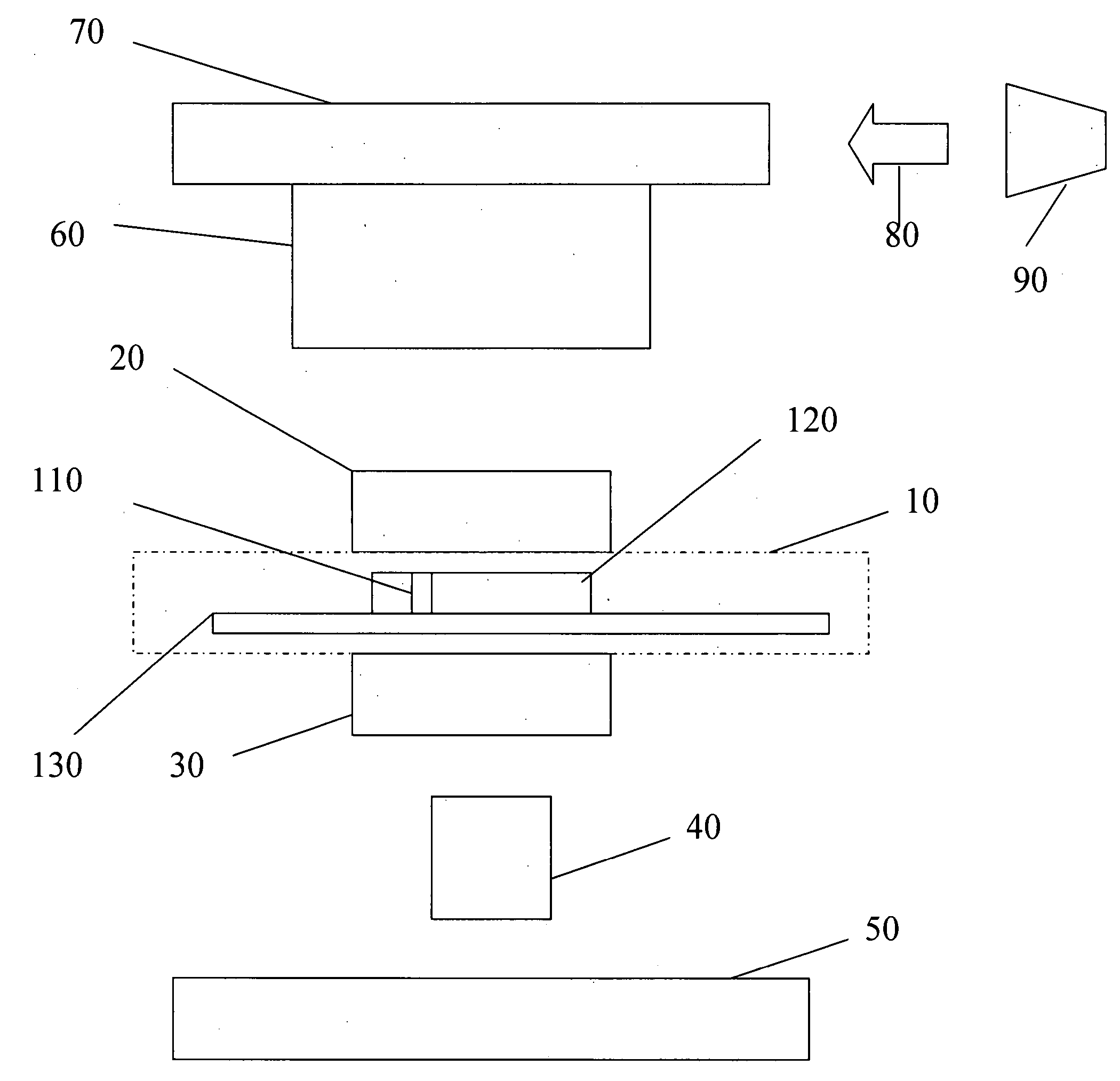
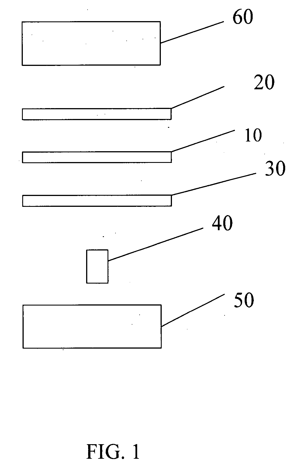
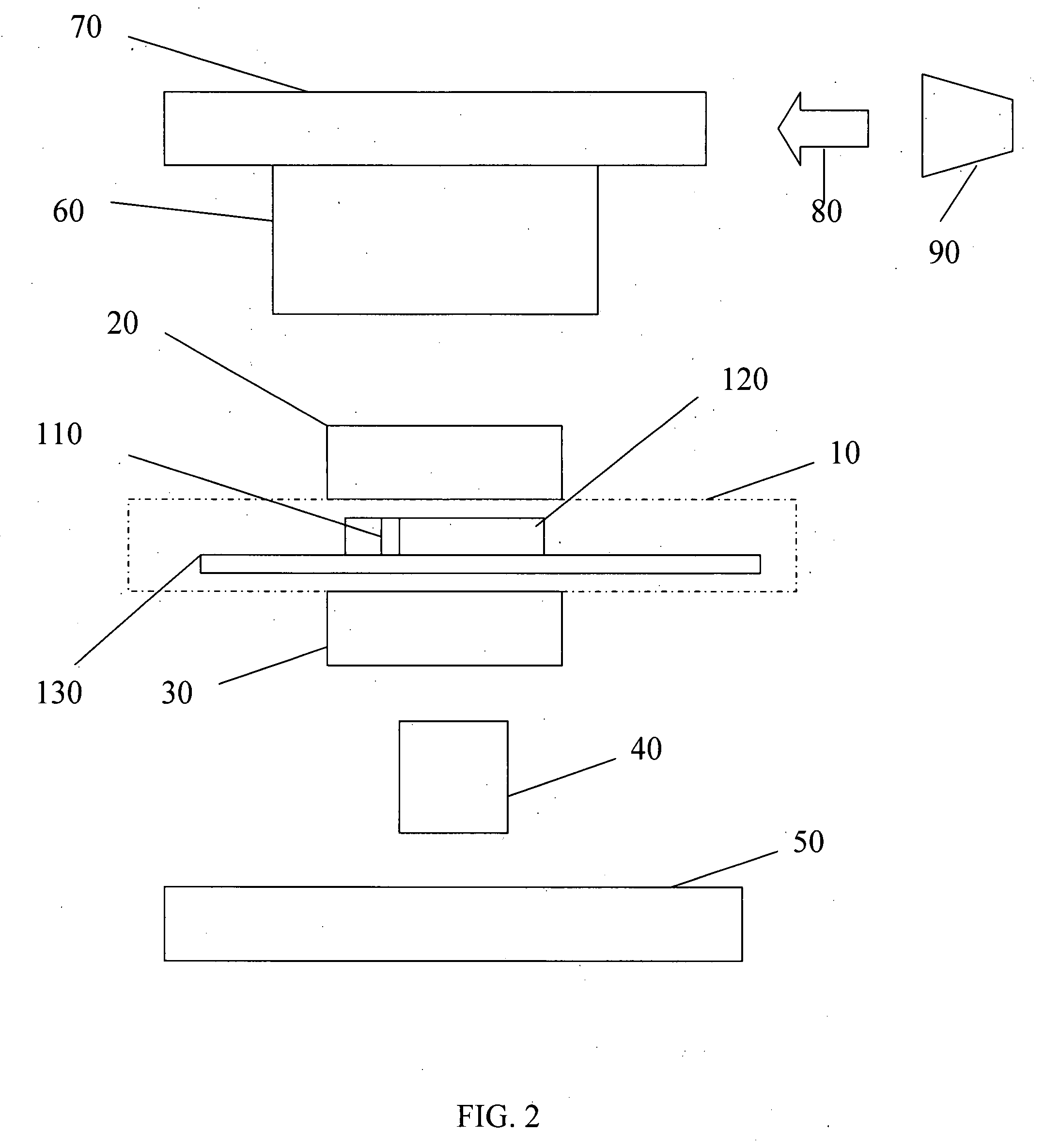
[0054] According to a first embodiment a microfluidic fluorescence assay detector and related methods are disclosed, the detectors to be used in combination with a microfluidic fluorescence assay apparatus, circuit or chip. In certain embodiments, the microfluidic fluorescence chip is a high-throughput multi-antigen fluorescence microfluidic assay chip, such as immunoassay-chips made from PDMS or or other polymers such as SIFEL, which can provide quantitative blood analysis at clinically relevant levels, such as 10-100 pM.

[0055] In Applicants' most recently developed immunoassay chips, active microfluidic matrix formats utilize arrays of integrated micromechanical valves to direct pressure-driven flow and to multiplex analyte samples with immunoassay reagents. ELISA-like fluorescence immunostacks are formed in the microchambers at the intersections of sample and reagent channels. In the present disclosure, Applicants show that the fluorescence signals of the captured antigens from ...


PUM

PropertyMeasurementUnit
Structureaaaaaaaaaa
Distanceaaaaaaaaaa
Frequencyaaaaaaaaaa

Abstract

Microfluidic assay detectors and microfluidic assay detection methods are disclosed. A microfluidic chip is coupled to a light emitting device, emission filters and excitation filters. Excited fluorescent light is detected by a camera and a lens. The correspondent reading allows parallel detection of features such as antigens and biomarkers. A microfluidic filter and related methods are also disclosed. The filter can be used with on-chip fluid filtration such as whole blood filtration for microfluidic blood analysis. The filter is able to filter the necessary volume of fluid and in particular blood in an acceptable time frame.

Description

RELATED APPLICATIONS [0001] The present application claims the benefit of provisional application 60 / 802,068 for “Personalized Medicine Device” filed on May 19, 2006 and incorporated herein by reference in its entirety. The present application also claims the benefit of provisional application 60 / 900,246 for “Microfluidic Device to Extract Blood Plasma from a Finger Stick” filed on Feb. 9, 2007, also incorporated herein by reference in its entirety. The present application is also related to U.S. patent application Ser. No. 11 / 439,288 “High Throughput Multi-Antigen Microfluidic Fluorescence Immunoassays” filed on May 22, 2006 and to U.S. patent application Ser. No. 11 / 297,651, “Prototyping Methods and Devices for Microfluidic Components”, filed on Dec. 7, 2005 all of which are also incorporated herein by reference in their entirety.GOVERNMENT INTEREST [0002] The U.S. Government has certain rights in this invention pursuant to DARPA grant no. HR0011-04-1-0032, NIH grant no. HG022644,...

Claims


Application Information

Patent Timeline
IPC IPC(8): G01N21/25B01D63/00F15C1/06F15C5/00
CPCG01N21/6456G01N21/6452Y10T137/2224
Inventor MALTEZOS, GEORGELEE, JOHN KIMSCHERER, AXELKARTALOV, EMIL
Owner CALIFORNIA INST OF TECH
Why Eureka
Try Eureka