Noncontact Ic Label and Method and Apparatus for Manufacturing the Same

Inactive Publication Date: 2008-02-21
TOPPAN MOORE CO LTD
View PDF24 Cites 28 Cited by
  • Summary
  • Abstract
  • Description
  • Claims
  • Application Information

AI Technical Summary

Benefits of technology

[0120] As explained above, according to the present invention, by forming a magnetic layer, the antenna coil can be made to generate sufficient induced electromotive force to operate the IC chip even in the case of being placed on a metal article. Moreover, since the magnetic layer can be formed thinly, compared with a conventional non-contact IC label, a non-contact IC label with a thin thickness can be provided.
[0121] Since the method of manufacturing the non-contact IC label according to the present invention involves continuously supplying a subst

Problems solved by technology

Because of this, the problem arises of the flux that crosses the antenna coil of the IC label decreasing, causing the induced electromotive force to drop below the actuation electromotive force of the IC chip, so that the IC chip does not operate (for example, refer to nonpatent document 1).
However, in the method disclosed in patent document 1, enlarging the diameter of the antenna coil 152 in order to increase the flux that passes the antenna coil 152 in order to increase the induced electromotive force gives rise to the problem of increasing the thickness of the IC label.
On the other hand, in the method disclosed in patent document 2, the problem arises of increased thickness of the IC label due to providing a magnetic core member and a conductive member on one surface of the substrate.
However, in protecting the IC chip by supplying resin onto a semiconductor substrate on whose base substrate the IC chip is mounted and sealing the semiconductor substrate with the resin as described above, at the juncture when resin is supplied on the semiconductor substrate, the IC chip may be damaged and the connections between the wiring formed on the base substrate and the IC chip may break from the pressure and heat of the resin supply.
In addition, in a semiconductor device whose semiconductor substrate, on whose base substrate an IC chip is mounted, is sealed with resin, the IC chip may be damaged and the connections between the wiring formed on the base substrate and the IC chip may break from pressure being applied to the IC chip due to expansion of the resin from changes in the surrounding environment after manufacture, particularly a rise in the ambient temperature.
However, since the magnetic moment of the ferromagnetic material having spontaneous magnetization characteristics is strong, there is strong magnetic isotropy in this ferromagnetic material.
Accordingly, in the IC label in which a magnetic layer consisting of a ferromagnetic material is provided so as to be in contact with the antenna, when picking up flux emitted from the information writing reading device, variations arise in the degree of flux capture, giving rise to the problem of a d

Method used


Image

  • Noncontact Ic Label and Method and Apparatus for Manufacturing the Same
  • Noncontact Ic Label and Method and Apparatus for Manufacturing the Same
  • Noncontact Ic Label and Method and Apparatus for Manufacturing the Same

Examples


first embodiment

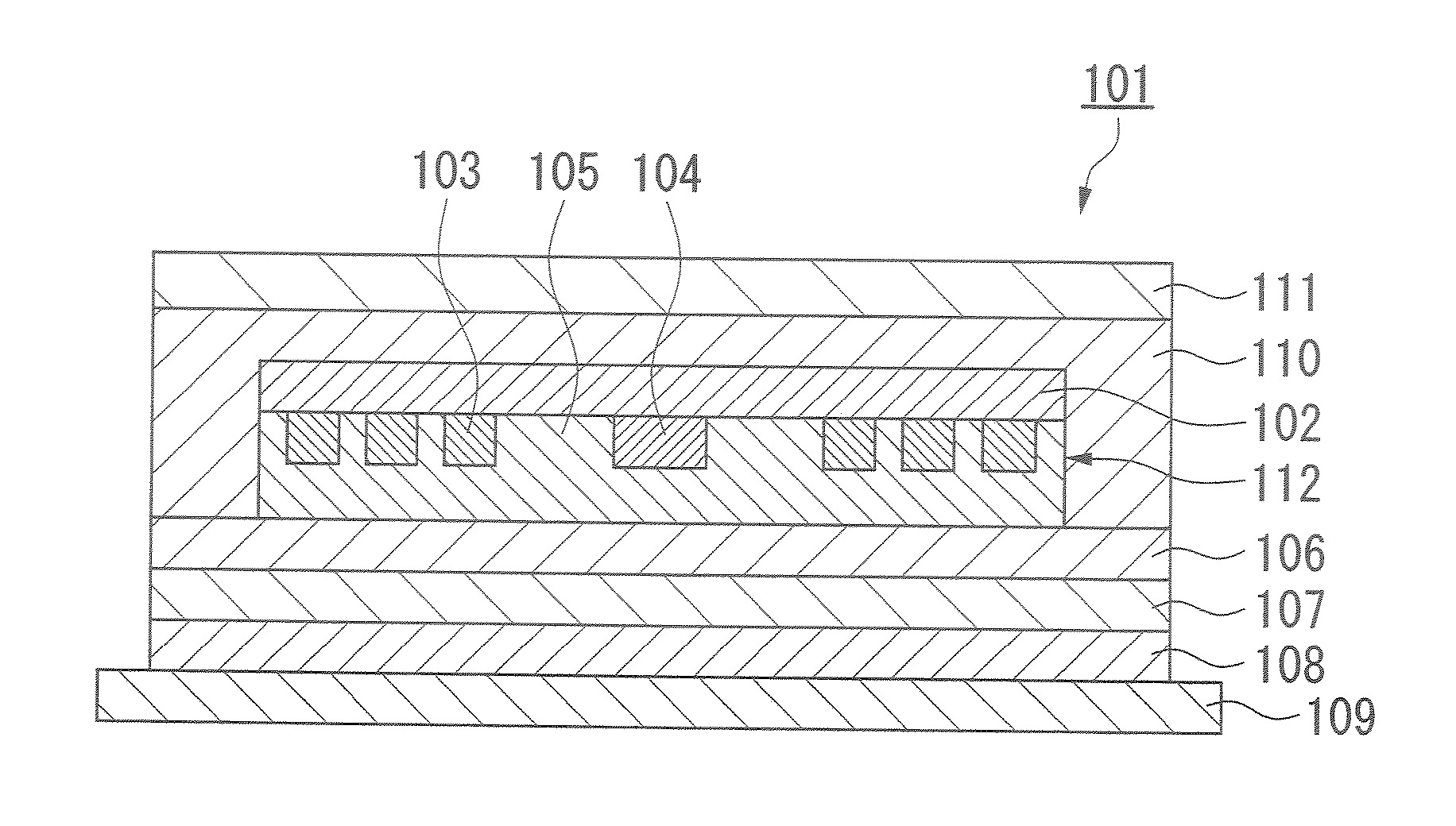
[0221]FIG. 1 is an outline sectional view of the non-contact IC label that is the present invention. In FIG. 1, an antenna coil 103 and an IC chip 104 are provided on one surface of an electrically insulating first substrate 102, with the antenna coil 103 and the IC chip 104 being electrically connected. On one surface of the first substrate 102, a magnetic layer 105 is provided so as to cover the antenna coil 103 and the IC chip 104, a first adhesive layer 106 is provided on the magnetic layer 105, an electrically insulating second substrate 107 is provided on the first adhesive layer 106, a second adhesive layer 108 is provided on the second substrate 107, and a release paper 109 is provided on the second adhesive layer 108. An overlay material 111 is provided on the other surface of the first substrate 102 via a third adhesive layer 110.

[0222] The first substrate 102 in this embodiment may be a publicly known material such as a woven fabric, non-woven fabric, mat, paper or combin...

second embodiment

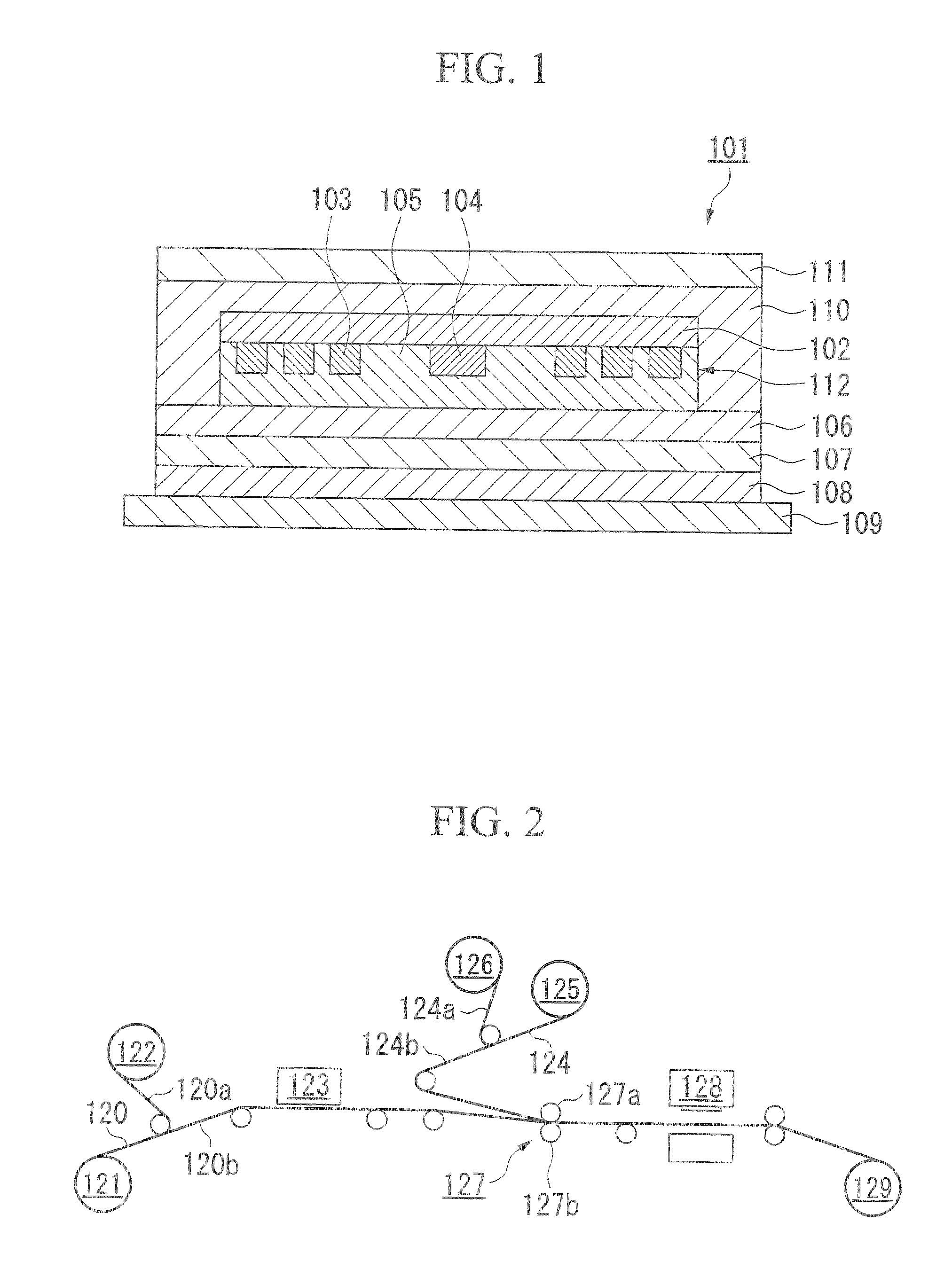
[0236]FIG. 2 is a drawing schematically showing the constitution of the apparatus for manufacturing the non-contact IC label 101 according to the present invention.

[0237] The manufacturing apparatus of the present embodiment is provided with a first supply means 121 that supplies a first continuous sheet 120 consisting of a backing paper attached to one surface of the second substrate 107 via the first adhesive layer 106 and the release paper attached to the other surface via the second adhesive layer 108.

[0238] After a backing paper 120a on the surface layer of the first continuous sheet 120 supplied from the first supply means 121 is peeled off and taken up by a take-up portion 122, the first continuous sheet 120 is sent to an inlet attaching means 123.

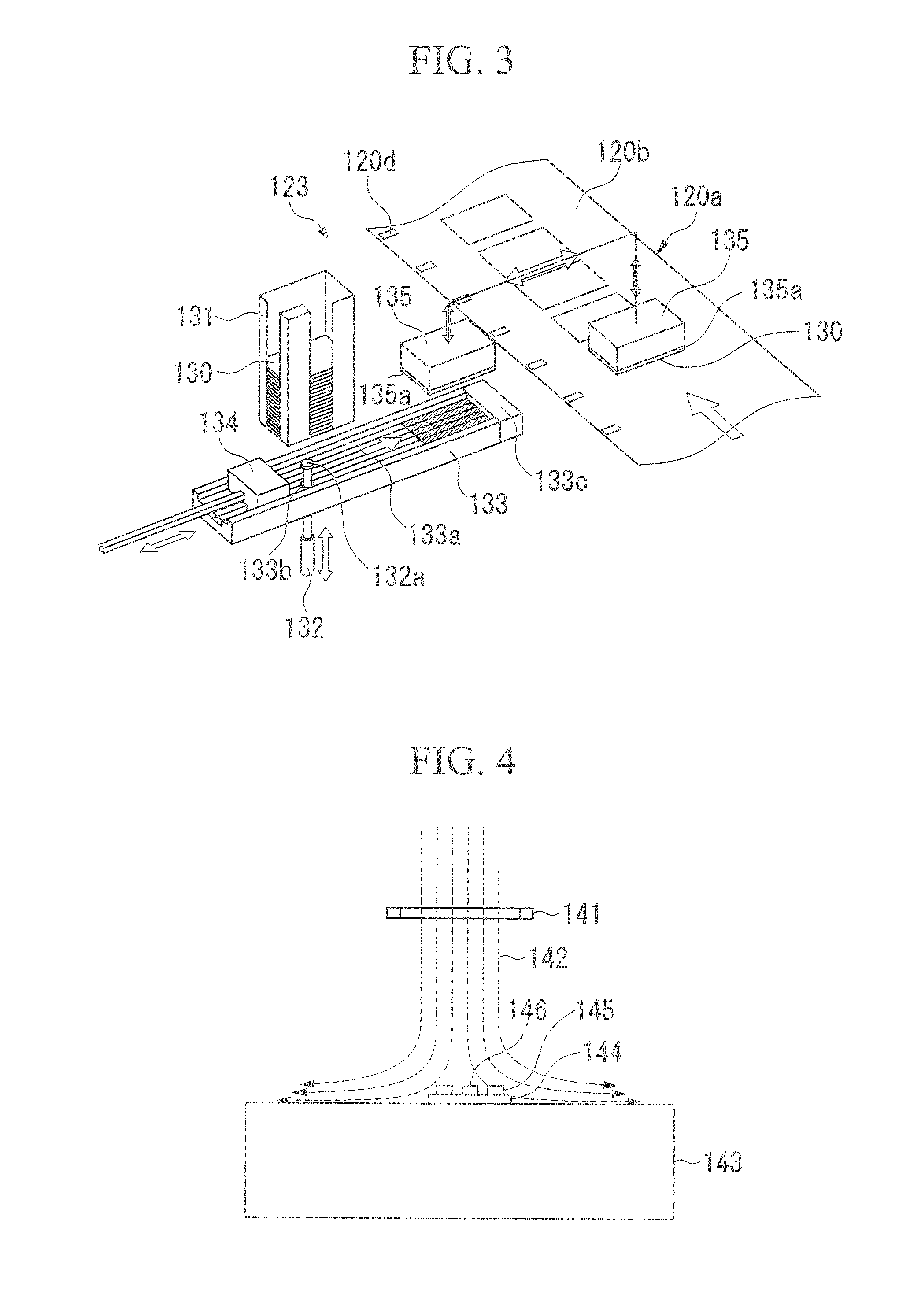
[0239] As shown in FIG. 3, the inlet attaching means 123 is provided with a stacker (holding means) 131 that holds a plurality of IC inlets 130 (corresponding to 112 in FIG. 1) in a vertically stacked state. Under the stacker 131,...

third embodiment

[0258]FIGS. 7A and 7B are schematic diagrams showing the non-contact IC tag that is the third embodiment according to the present invention, with FIG. 7A being a plan view showing the internal structure and FIG. 7B being a sectional view along line A-A of FIG. 7A.

[0259] In FIGS. 7A and 7B, reference numeral 210 denotes a non-contact IC tag, 211 a base substrate, 212 an antenna, 213 an IC chip, 214 contacts 215 an inlet, 220 a magnetic layer, 221 a first resin member 222 a recessed portion, 223 a second resin member, and 225 a case.

[0260] This non-contact IC tag 210 is roughly constituted from an inlet 215 including a base substrate 211 and an electrically connected antenna 212 and IC chip 213 provided on one surface thereof; a magnetic layer 220 disposed so as to cover the antenna 212 and the IC chip 213 constituting the inlet 215; and a case 225 including a first resin member 221 and a second resin member 223 provided so as to envelop the inlet 215 with the disposed magnetic layer...


PUM


Abstract

A non-contact IC label comprising an electrically insulating first substrate; an electrically connected antenna coil and IC chip provided on one surface of said substrate; a magnetic layer provided on said one surface of said substrate so as to cover said antenna coil and said IC chip, a first adhesive layer provided on said magnetic layer, an electrically insulating second substrate provided on said first adhesive layer, a second adhesive layer provided on said second substrate, a release paper provided on said second adhesive layer, and an overlay material provided on a third adhesive layer on the other surface of said first substrate.

Description

TECHNICAL FIELD [0001] The present invention relates to a non-contact data reception / transmission unit such as a non-contact IC label that can receive information from outside and send information to the outside through the medium of electromagnetic waves, such as information storage media of an RFID (Radio Frequency IDentification) application. [0002] The present invention relates to a semiconductor device and a manufacturing method therefor, and particularly relates to a semiconductor device in which a semiconductor substrate consisting of an IC chip mounted on a base substrate is sealed in resin and its manufacturing method. [0003] The present application claims priority on Japanese Patent Application No. 2004-299307, filed Oct. 13, 2004; Japanese Patent Application No. 2004-335100, filed Nov. 18, 2004; Japanese Patent Application No. 2004-335101, filed Nov. 18, 2004; Japanese Patent Application No. 2005-038963, filed Feb. 16, 2005; Japanese Patent Application No. 2005-038964, fi...

Claims


Application Information

Patent Timeline
IPC IPC(8): G06K19/06H01L21/00H01L23/34
CPCG06K19/07718G06K19/07749H01L2924/0002G06K19/07771H01F17/0006H01F41/041H01L23/3121H01L23/48H01L23/5227H01L2924/09701H04B5/0062H04B5/0081H04B5/02H01L2924/00G06K19/077B42D25/305H01F17/00
Inventor KAGAYA, HITOSHIIDE, YOSHIAKIYAMAKAMI, TAKESHIOHNO, HIROKI
Owner TOPPAN MOORE CO LTD
Why Eureka
Try Eureka