Wear-resistant coating and process for producing it

a technology of wear-resistant coating and process, applied in the direction of superimposed coating process, machine/engine, transportation and packaging, etc., can solve the problems of reducing affecting the service life of valve gear, etc., to achieve the effect of reducing the friction coefficien

Inactive Publication Date: 2008-02-21
INA SCHAEFFLER KG
View PDF6 Cites 26 Cited by
  • Summary
  • Abstract
  • Description
  • Claims
  • Application Information

AI Technical Summary

Benefits of technology

[0013] Therefore, it is an object of the present invention to provide a wear-resistant coating and a process for producing a coating of this type which eliminate the abovementioned drawbacks and in particular ensure wear resistance over the entire service life of an internal combustion engine with a reduced friction coefficient.
[0015] The idea of the present invention is based consists of a wear-resistant coating on predetermined surfaces of machine or engine parts which are exposed to frictional wear consisting of at least one metal-free, amorphous hydrocarbon layer which includes sp2- and sp3-hybridized carbon applied to the predetermined surface of the machine or engine part in order to reduce friction and increase the wear resistance of the predetermined surface of the machine or engine part.
[0016] The present invention has the advantage over the prior art that the wear resistance, for example in the sliding contact with the camshaft in the case of shiftable drag levers, is increased compared to the prior art. Furthermore, the friction in the sliding contact with the camshaft in shiftable drag levers is reduced, as compared to the prior art. Moreover, the drag levers or other machine or engine parts can be produced at low cost, on account of the process involving low manufacturing costs.
[0017] According to a preferred refinement, the amorphous hydrocarbon layer has a hydrogen content of at most 16 atomic %. As a result, the predetermined surface of the machine part or drag lever has little tendency to adhere to the metallic opposing body, i.e. the cam, a high resistance to abrasive wear, a high chemical stability, high mechanical strength and high hardness / elasticity modulus ratios. A higher hydrogen content could lead to undesirable compounds being formed with lubricants or the like.
[0019] According to a further preferred embodiment, the overall coating is from approximately 1.0 mm to 5.0 mm thick, with the amorphous hydrocarbon layer preferably being from 0.8 mm to 2.5 mm thick. Layer thicknesses of this nature cause such a slight change to the dimensions of the machine or engine parts that there is no need for any further processing, and the surface structure or topography which has been set may be maintained.

Problems solved by technology

The fact that considerable wear, which reduces the service life of the valve gear, can occur as a result of the friction between a supporting element and a spherical cap-shaped cutout, i.e. steel-steel friction, has proven to be disadvantageous for the drag lever described in this document.
However, one drawback which has been found for this approach is that metal layers applied by thermal spraying have a relatively low strength.
If the proportion of base material is too high, the wear to the layer then becomes too high, and if the proportion of base material is low, in some layer combinations there is a risk of the formation of macrocracks, which means that these layers cannot be used.
In such a case, frictional loading may cause undesirable adhesive wear to the layers.
However, it has been found that despite the resulting surface hardening, high levels of wear continue to occur at high contact pressures, as before.
However, the fact that the individual process steps are complex and expensive and do not provide sufficient wear resistance has proven to be a drawback of this prior art approach.
However, the fact that the known coatings do not offer sufficient resistance to wear under the lubricating conditions and contact pressures which occur with shifting drag levers has proven to be disadvantageous for these prior art approaches.
A further drawback is that the friction caused by the sliding surfaces in the system with shifting drag levers cannot be compensated for by conventional coating processes.
Furthermore, additionally soldered-on hard metal plates increase both the costs and the mass of the individual drag levers in a detrimental way.

Method used


Image

  • Wear-resistant coating and process for producing it
  • Wear-resistant coating and process for producing it
  • Wear-resistant coating and process for producing it

Examples


Embodiment Construction

[0030] In the Figures, identical reference designations denote identical or functionally equivalent components unless stated otherwise.

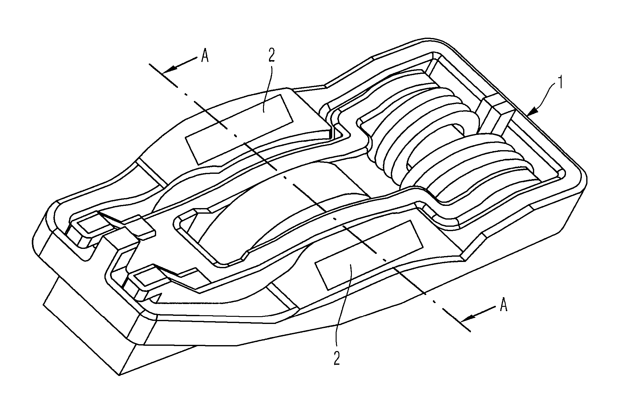
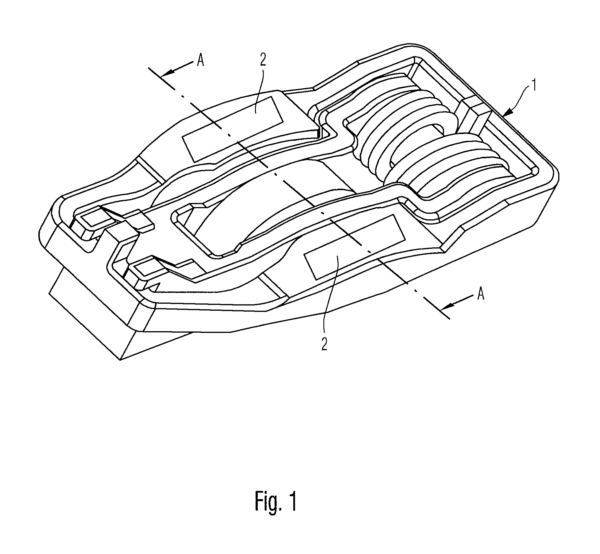
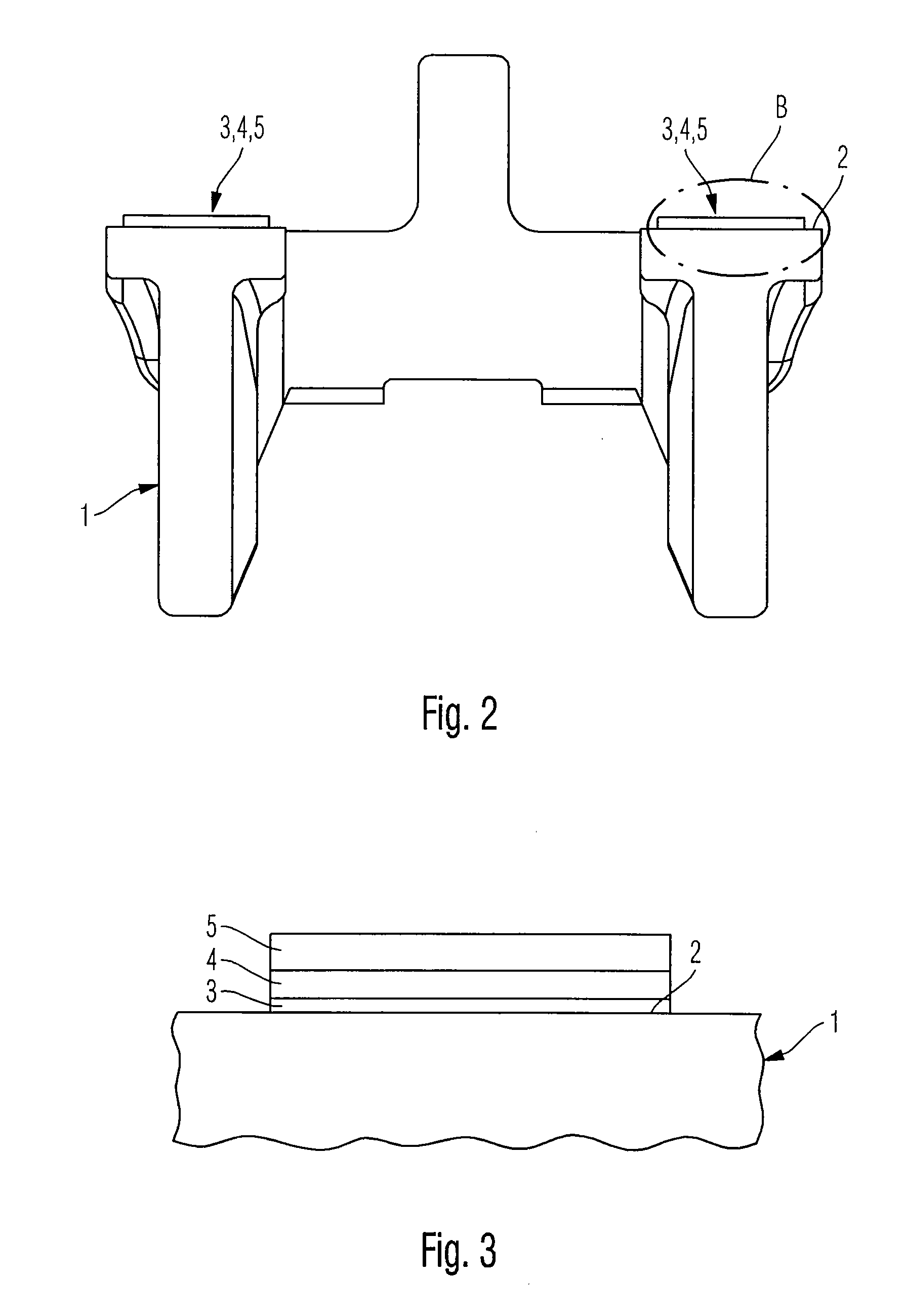
[0031]FIG. 1 illustrates a perspective view and FIG. 2 a cross-sectional view on line A-A from FIG. 1 of a shiftable drag lever 1 in accordance with an embodiment of the present invention. The lever is used in the valve gear of internal combustion engines for switching off valves / cylinders and / or switching over the valve stroke. According to the present embodiment, the drag lever 1 has two sliding surfaces 2 which are arranged symmetrically with respect to one another and against which a mating body, for example a camshaft (not shown), comes to bear frictionally. The drag lever 1, particularly in the region of the sliding surfaces 2, is subject to wear as a result of the frictional pairing with the associated camshaft. It is therefore desirable for these sliding surfaces 2 of the shifting lever 1 to be provided with wear protection or a wear-resista...


PUM

PropertyMeasurementUnit
thickaaaaaaaaaa
thickaaaaaaaaaa
thickaaaaaaaaaa

Abstract

A process for producing a wear-resistant coating and a wear-resistant coating on a surfaces of machine or engine parts which are exposed to frictional wear. This has in particular use for internal combustion engines. The coating comprises at least one metal-free, amorphous hydrocarbon layer which includes sp2- and sp3-hybridized carbon applied to the surface of the machine part, for reducing friction and increasing the wear resistance of the surface of the machine or engine part.

Description

CROSS-REFERENCE TO RELATED APPLICATION [0001] This application is a divisional of U.S. patent application Ser. No. 11 / 211,052, filed Aug. 24, 2005, entitled WEAR-RESISTANT COATING AND PROCESS FOR PRODUCING IT, which claims priority to German Application No. 102004041234.0, filed Aug. 26, 2004, the contents of which are incorporated by reference.FIELD OF THE INVENTION [0002] The present invention relates to a wear-resistant coating on predetermined surfaces of machine or engine parts which are exposed to frictional wear, and to a process for producing a wear-resistant coating of this type, in particular for machine or engine parts in internal combustion engines. [0003] Although it can be applied to any desired machine or engine parts, the present invention and the object on which it is based are explained in more detail in connection with engine parts for internal combustion engines, in particular on the basis of a shiftable drag lever which can be used in the valve gear of an intern...

Claims


Application Information

Patent Timeline
Patent Type & Authority Applications(United States)
IPC IPC(8): B32B5/16
CPCC23C14/024C23C14/0605C23C16/0272C23C16/26F01L1/185F01L13/0036Y10T428/256F01L2103/00F01L2105/00C23C28/044C23C28/046F01L2820/01Y10T428/30F01L2101/00F01L2301/00F01L2303/00F01L2305/00C09D5/00
Inventor RORIG, BODOHOSENFELDT, TIM MATTHIAS
Owner INA SCHAEFFLER KG
Why Eureka
Try Eureka