Method for forming resist pattern, semiconductor device and production method thereof

a semiconductor device and resist pattern technology, applied in the field of methods, can solve the problems of difficult to develop resist materials suitable for shorter wavelengths, inability to form finer wiring patterns, and inability to meet the requirements of shortening the wavelength of exposure lights, so as to achieve uniform thickness, improve the effect of uniform thickness, and ensure the desired thickness level

Inactive Publication Date: 2008-02-21
FUJITSU LTD
View PDF19 Cites 5 Cited by
  • Summary
  • Abstract
  • Description
  • Claims
  • Application Information

AI Technical Summary

Benefits of technology

[0017]It is an object of the present invention to provide a method for forming a resist pattern, in which ArF excimer laser light can be utilized as the exposure light for the patterning, the resist patterns can be thickened stably to an intended thickness independently of the sizes of the resist patterns, and thus the fineness of the fine space patterns can surpass the limit in terms of exposure or resolution of exposure devices.
[0018]Another object of the present invention is to provide a method for producing a semiconductor device, in which ArF excimer laser light can be utilized as the exposure light for the patterning, the fineness of the fine space patterns can surpass the limit in terms of exposure or resolution of exposure devices, and high performance semiconductor devices can be effectively mass-produced with fine wiring patterns formed using the fine space patterns. Another object of the present invention is to provide a high performance semiconductor device having fine wiring patterns produced in accordance with the inventive method.
[0024]The inventive method for producing a semiconductor device comprises a step of forming a resist pattern, in which a resist pattern is formed by the inventive method for forming a resist pattern, and a step of patterning, in which the processing surface is patterned by etching using the resist pattern as a mask. In the method for producing the semiconductor device, a resist pattern is initially formed on the processing surface, to which a pattern such as wiring pattern being formed, in the step of forming the resist pattern. Accordingly, the thickened resist patterns can be uniformly increased in its thickness without depending on the sizes or density fluctuation of the resist pattern, and the desirable thickening level can be sufficiently assured without depending on the species of resist materials. Consequently, thickened resist patterns can be formed easily and precisely, in addition to contact hole patterns, such as line patterns utilized for LOGIC LSI wiring layers in semiconductor devices where resist patterns exit in various sizes.
[0025]Subsequently, the processing surface is finely and precisely patterned with higher dimensional accuracy in the patterning step by way of etching thereof using the resist pattern thickened in the step of forming the resist pattern, thereby high-quality, high-performance semiconductor devices can be efficiently produced with precise and fine patterns including wiring patterns having higher dimensional accuracy.
[0026]The inventive semiconductor devices are produced by the inventive method for producing a semiconductor device. The semiconductor devices can have highly precise and accurate patterns such as wiring patterns with higher dimensional accuracy.

Problems solved by technology

However, the development to shorten the wavelength of the exposure lights inevitably involves costly improvement of exposure devices.
Furthermore, it is not easy to develop resist materials suitable for shorter wavelengths.
However, there exist a problem in the RELACS technology that the ArF excimer laser light cannot be utilized and thus finer wiring patterns cannot be formed by reason that the KrF resists are aromatic resin compositions including a novolak resin, naphthoquinonediazide resin etc., the aromatic ring contained in the aromatic resin compositions allows KrF excimer laser light of wavelength 248 nm to pass through, but absorbs ArF excimer laser light of wavelength 193 nm, i.e. a shorter wavelength, thus inhibits the ArF excimer laser light to pass through.
Moreover, there is another problem in the RELACS technology that the resist swelling agent is effective for thickening or swelling the KrF resist but not effective for thickening or swelling the ArF resist.
In addition, the resist swelling agent has lower etch resistance itself, thus, when an ArF resist pattern having lower etch resistance is swelled, the same dimension as the swelled pattern cannot be patterned on the substrate to be processed.
Furthermore, even if KrF resist having relatively satisfactory etch resistance is swelled there is still another problem that the etching cannot be precisely carried out and patterns having the same dimension as the swelled pattern cannot be obtained, in such cases where etching condition is severe, or where the KrF resist pattern is fine, or where the resist film is thin, or the like.
When X-rays or electron beams having wavelengths shorter than that of the ArF excimer laser light is used as the exposure light, however, it results in remarkably higher costs and lower productivity.
However, the composition of this resist pattern thickening material is likely to cause a dependency on the pattern size before thickening, that is, when the pattern size before thickening increases, the reduced level of the pattern size after thickening may enlarge in proportion to the pattern size.
Furthermore, there appear a difference in the shrinking levels in accordance with the pattern densities, and the pattern sizes after shrinking at relatively dilute regions having longer distances between resist patterns are liable to be different from those at relatively dense regions having shorter distances between resist patterns; more specifically, the more dense are the resist patterns the larger are likely to be the shrinking levels of the pattern size after the thickening.
However, the aforesaid resist pattern thickening material containing benzylalcohol may represent insufficient thickening effect depending on the species of the resist materials and / or may bring about nonuniform thickening effect depending on pattern layouts, although they can show less size-dependency.

Method used


Image

  • Method for forming resist pattern, semiconductor device and production method thereof
  • Method for forming resist pattern, semiconductor device and production method thereof
  • Method for forming resist pattern, semiconductor device and production method thereof

Examples


example 1

[0167]The hole patterns, formed in accordance with the same procedure as the thickening experiment of resist pattern described above, were thickened using the resist pattern thickening materials B and D under the conditions below.

Condition

[0168]1. coating: two times, baking: one time, developing: one time;

[0169]2. coating and baking: each two times, developing: one time;

[0170]3. coating and baking: each five times, developing: one time;

[0171]4. coating and baking and developing: each two times;

[0172]5. coating and baking and developing: each five times.

[0173]In the conditions 1 to 5 described above, the coating, the baking and the developing were respectively carried out in accordance with the same procedures as those of the thickening experiment of resist pattern described above; when these steps were carried out plural times, they were repeatedly carried out under the same conditions.

[0174]The thickened levels of the resulting resist patterns are shown in Table 3 in terms of the d...

example 2

[0177]Thickened resist patterns were formed using the resist pattern thickening materials B and D shown in Table 1 described above. The thickened patterns were trench patterns of various sizes of space or trench shown in “Space Pattern Size before Thickening” in Table 4, which were formed from an alicyclic ArF resist (GAR-D05, by Fuji Film Electronic Materials Co.). The trench patterns were thickened to prepare thickened resist patterns under the conditions 4 and 5 shown in Example 1 and the normal condition.

[0178]The decreased level (mm) of the space pattern size formed from the resulting thickened resist pattern was shown in Table 4 in terms of the difference of space pace pattern sizes between before and after the thickening along with the initial pattern size before the thickening.

TABLE 4Decreased Levelof SpaceSpace Pattern SizePattern Size afterbefore ThickeningThickening (nm)Condition(nm)Material BMaterial Dnormalcoating, baking and developing126.06.915.2192.09.018.0269.010.62...

example 3

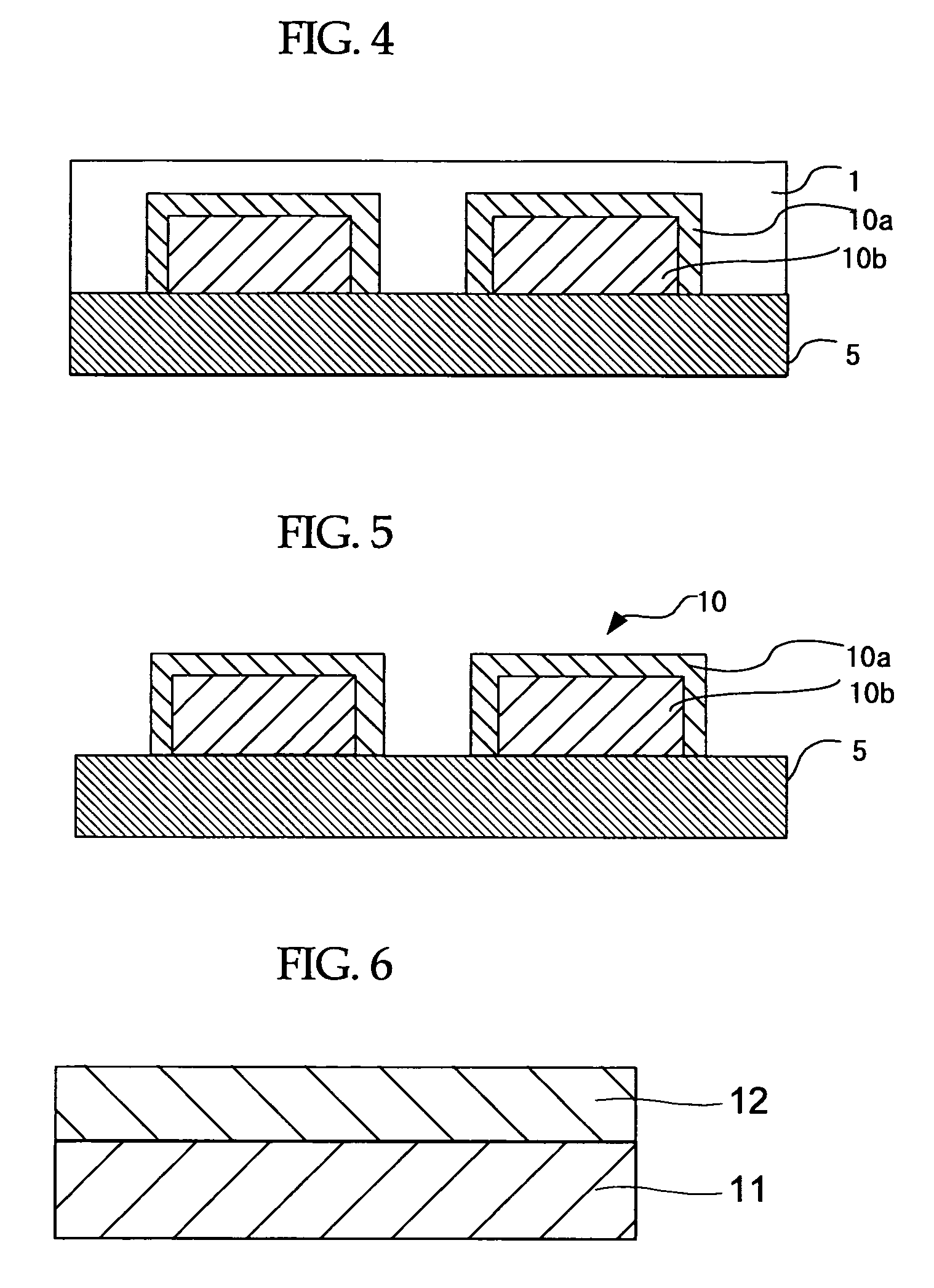
[0181]As shown in FIG. 6, interlayer dielectric film 12 was formed on silicon substrate 11, and as shown in FIG. 7, titanium film 13 was formed by a sputtering process on the interlayer dielectric film 12. Then as shown in FIG. 8, resist pattern 14 was formed by a conventional photolithographic process. By using the resist pattern 14 as a mask, the titanium film 13 was patterned by reactive ion etching to form openings 15a. Reactive ion etching was continuously carried out to remove the resist pattern 14, at the same time, as shown in FIG. 9, openings 15b were formed in the interlayer dielectric film 12 by using the titanium film 13 as a mask.

[0182]Then the titanium film 13 was removed by a wet process, and as shown in FIG. 10, TiN film 16 was formed on the interlayer dielectric film 12 by a sputtering process. Subsequently Cu film 17 was grown by an electrolytic plating method on the TiN film 16. Then as shown in FIG. 11, planarizing was carried out by CMP such that the barrier met...


PUM

PropertyMeasurementUnit
relative permittivityaaaaaaaaaa
wavelengthaaaaaaaaaa

Abstract

It is an object of the present invention to provide a method for forming a resist pattern, in which ArF excimer laser light can be utilized as the exposure light for the patterning, the resist patterns can be thickened stably to an intended thickness independently of the sizes of the resist patterns, and the fineness of the fine space patterns can surpass the limit in terms of exposure or resolution of exposure devices.The method for forming a resist pattern of the present invention comprises at least forming a resist pattern, coating a resist pattern thickening material to cover the surface of the resist pattern, baking the resist pattern thickening material, and developing and separating the resist pattern thickening material, wherein at least one of the coating, the baking and the developing is carried out plural times.

Description

CROSS-REFERENCE TO RELATED APPLICATIONS[0001]This application is based upon and claims the benefits of the priority from the prior Japanese Patent Application No. 2006-222498, filed on Aug. 17, 2006, the entire contents of which are incorporated herein by reference.BACKGROUND OF THE INVENTION[0002]1. Field of the Invention[0003]The present invention relates to methods for forming resist patterns, which being applied over resist patterns of semiconductor devices in order to thicken or to increase the thickness of the resist patterns, thereby forming fine space patterns of which the fineness can surpass a limit in terms of exposure or resolution of light sources in available exposure devices. The present invention also relates to semiconductor devices and production methods thereof.[0004]2. Description of the Related Art[0005]Semiconductor integrated circuits have been highly integrated, and LSIs and VLSIs have been come into practical use. Accompanying this trend, the wiring patterns...

Claims


Application Information

Patent Timeline
Patent Type & Authority Applications(United States)
IPC IPC(8): G03C5/00
CPCG03F7/40H01L21/31144H01L21/0273
Inventor KOZAWA, MIWANOZAKI, KOJI
Owner FUJITSU LTD
Why Eureka
Try Eureka