
High-Luminance Quantum Correlation Photon Beam Generator

a generator and quantum correlation technology, applied in the field of high-luminance quantum correlation photon beam generators, can solve the problem that the efficiency of generating quantum correlated photon pairs is not enough, and achieve the effect of improving the efficiency of generating quantum correlated photon pairs obtained from parametric crystals

Inactive Publication Date: 2008-02-28
JAPAN SCI & TECH CORP
View PDF3 Cites 4 Cited by
  • Summary
  • Abstract
  • Description
  • Claims
  • Application Information

AI Technical Summary

Benefits of technology

[0007] Then, the present Invention has been accomplished in view of the above circumstances. It is an object of the present invention to provide a high-luminance quantum correlation photon beam generator which can solve the problem of the conventional technique and can further improve the efficiency of generating quantum correlated photon pairs obtained from a parametric crystal.
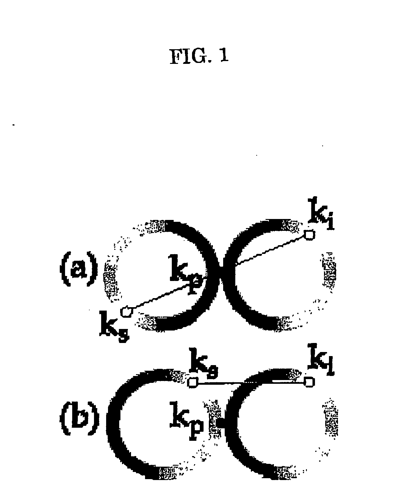
[0017] According to the invention of this application, all of the annular parametric fluorescence pairs can be quantum correlated without cutting out a part of the annular parametric fluorescence pairs emitted from the parametric crystal by a pin hole for quantum correlation. Accordingly, the efficiency of generating quantum correlated photon pairs obtained from a parametric crystal can be improved dramatically.

Problems solved by technology

Since the remaining ones could not be used, the efficiency of generating quantum correlated photon pairs is not enough.

Method used


Image

  • High-Luminance Quantum Correlation Photon Beam Generator
  • High-Luminance Quantum Correlation Photon Beam Generator
  • High-Luminance Quantum Correlation Photon Beam Generator

Examples


example

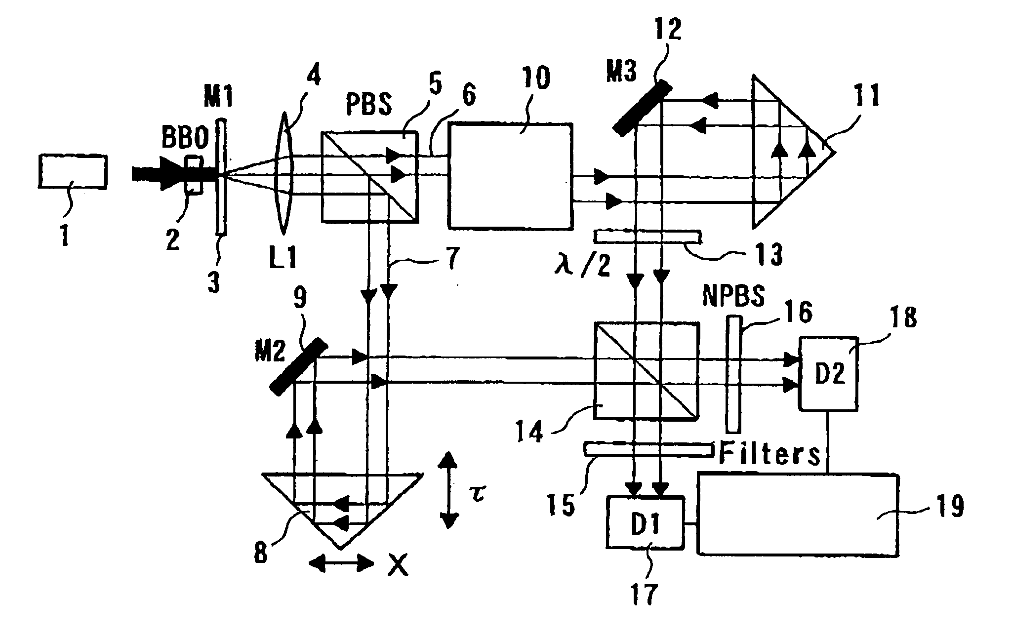
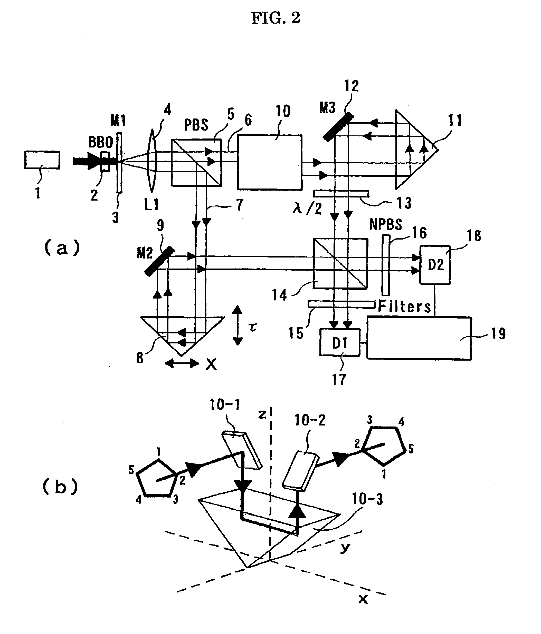
[0044] An apparatus in the configuration shown in FIG. 2 was used to generate quantum correlated photon beams. For a laser apparatus (1), a Ti:sapphire laser apparatus emitting pulse laser light was used (Tsunami, manufactured by Spectra Physics, Inc., where a pulse length was 100 fs, a center frequency was 800 nm, and a repetition frequency was 80 MHz). For the BBO crystal (2), a Type II parametric down-conversion crystal having a thickness of 0.5 mm was used. The relative phase between the signal light beam (6) and the idler light beam (7) was changed by adjusting the position of the prism (8) to control an optical time delay τ. The generated quantum correlated photon pairs were received by the photodiode D1 (17) and D2 (18) (SPCM-AQR-14, manufactured by Perkin Elmer Corp.) through the interference filters (15) and (16) having a band width of 10 nm (FWHM), and counted by the coincidence counter (19) (single photon counter (SR400, manufactured by Stanford Research Systems, Inc.)). ...


PUM

PropertyMeasurementUnit
repetition frequencyaaaaaaaaaa
pulse lengthaaaaaaaaaa
thicknessaaaaaaaaaa

Abstract

A high-luminance quantum correlation photon beam generator a photon beam of a quantum correlated pair characterized by includes: a laser light source (1) operable to emit a laser pumped light; a parametric crystal (2) operable to generate a pair of two photons of a signal photon and an idler photon on receiving the pumped light from the laser light source (1) to emit two photon beams along two non-concentric cones; a beam splitting means (5) operable to split a signal photon beam (6) from an idler photon beam (7); a mode inverter (10) operable to rotate one of the annular signal photon beam (6) and the idler photon beam (7) 180° around its geometric center; a phase adjusting means (8) operable to adjust phases of the signal photon beam (6) and the idler photon beam (7) based on an optical time delay; and a beam coupling means (14) operable to overlay the signal photon beam (6) with the idler photon beam (7) in a common-line polarized annular shape by the mode inverter (10) to bring them into a quantum correlated state.

Description

TECHNICAL FIELD [0001] The present invention relates to a high-luminance quantum correlation photon beam generator. More specifically, the present invention relates to a high-luminance quantum correlation photon beam generator which can highly efficiently generate beams formed of a quantum correlated photon pair that are produced from a parametric crystal. BACKGROUND OF THE INVENTION [0002] In recent years, attention is focused on quantum information processing such as a quantum cryptography system, quantum teleportation, and a quantum computer, and quantum lithography using the principles of quantum mechanics (for example, C. Bennet and P. Shor, IEEE Trans. Inf. Theory 44, p. 2724 to 2742 (1998), and A. Boto, P. Kok, D. Abrams, S. Braunstein, C. Williams, and J. Dowling, Phys. Rev. Lett. 85 (13), p. 2733-6 (2000)). For these, a quantum correlated photon pair is used which is so called “quantum entanglement.” This phenomenon called quantum entanglement is that a single photon (pumpe...

Claims


Application Information

Patent Timeline
Patent Type & Authority Applications(United States)
IPC IPC(8): G02F1/39
CPCB82Y10/00G06N99/002G02F1/39G06N10/00
Inventor JARUTIS, VYGANDASMIZEIKIS, VYGANTASJUODKAZIS, SAULIUSMISAWA, HIROAKI
Owner JAPAN SCI & TECH CORP
Learn More