Reusable surgical perioperative positioning system

a positioning system and surgical technology, applied in the field of medical positioning systems, can solve the problems of poor stability of fairly crude positioning devices, inability to facilitate appropriate safety, and inability to provide adequate safety, and achieve the effects of avoiding high interface pressure points, and reducing the risk of complications

a positioning system and surgical technology, applied in the field of medical positioning systems, can solve the problems of poor stability of fairly crude positioning devices, inability to facilitate appropriate safety, and inability to provide adequate safety, and achieve the effects of avoiding high interface pressure points, and reducing the risk of complications

US20080052834A1Inactive Publication Date: 2008-03-06NOVA HEALTH CARE SYST

Image

  • Reusable surgical perioperative positioning system
  • Reusable surgical perioperative positioning system
  • Reusable surgical perioperative positioning system

Examples


Embodiment Construction

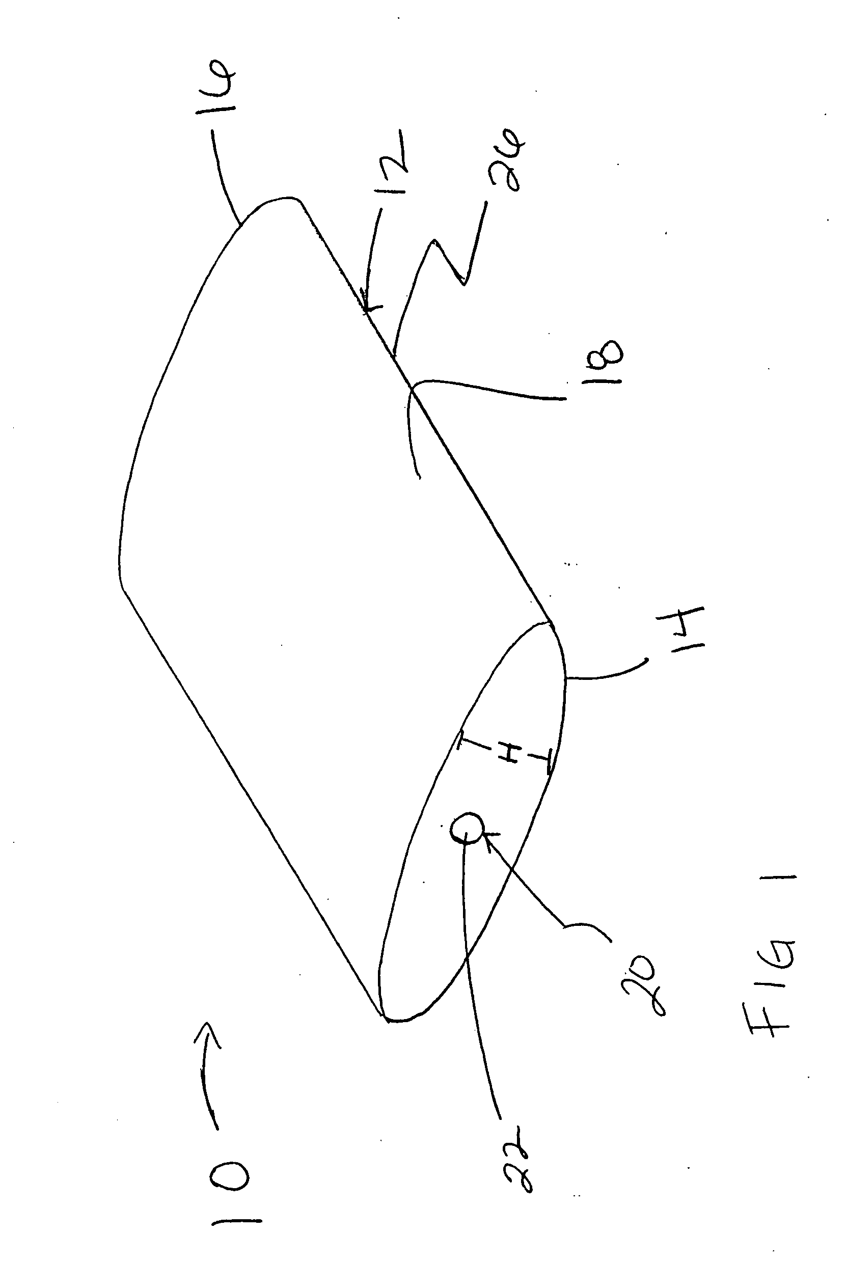
[0063] Referring initially to FIG. 1, a positioning system 10 in accordance with the invention includes at least one pad, cushion or pillow 12 that is constructed from a foam core (not shown) and a cover 26. Exemplary cushion 12 includes two elliptical or circular shaped ends 14, 16 and an oblong shaped body portion 18. Positioning system pads may include operating room table pads, stretcher pads and positioning pads.

[0064] In one embodiment, valve 20 is located on or within elliptical end 14. Valve 20 is not limited to this location, however, and may be located on or within any suitable surface of cushion 12 including oblong body portion 18.

[0065] Valve 20 is generally a lid, plug, or cover 22 applied to an aperture (not shown) so that by its movement, as by swinging, lifting and falling, sliding, turning, etc., valve 20 will open or close the aperture to permit or prevent passage of a fluid (not shown) such as air. The form of valve 20 is not particularly important so long as it...


PUM


Abstract

A support system including a cushion or pad having a foam core and cover is disclosed. The support system is capable of taking a variety of different shapes and can be adjusted for firmness. The support system may be used during and after surgery and more generally, any time when it is desirable to utilize a sterilizable, adjustable cushion. Additionally, multiple cushions may be used in a variety of combinations at any one time.

Description

RELATED APPLICATION [0001] The present application claims the benefit of U.S. Provisional Application No. 60 / 841,034 filed Aug. 30, 2006, entitled ā€œPositioning System for Use in a Perioperative Environmentā€ which is incorporated herein in its entirety by reference.FIELD OF THE INVENTION [0002] The present invention relates generally to the field of medical positioning systems including pads and cushions that are used in a perioperative environment. BACKGROUND OF THE INVENTION [0003] The perioperative environment includes surgical operating rooms and related areas of hospitals and surgical centers. The perioperative environment includes but is not limited to: the operating room, one day surgery areas, trauma units, critical care areas, plastic surgery, neonatal intensive care, patient transportation, obstetrics, the post anesthesia care unit, radiology, X-ray, the electrophysiology lab, nursing services and the neonatal care unit. [0004] During surgery, a patient may spend a great de...

Claims


Application Information

Patent Timeline
06 Mar 2008
Publication
US20080052834A1
IPC
A47C16/00
CPC
A61G7/065; A61G7/1021; A61G13/12; A61G13/121; A61G13/1225; A61G13/1235; A61G2200/34; A61G13/125
Inventors
HILL, DARRELL G.