Fullerene nanotube compositions

a technology of compositions and carbon nanotubes, applied in the field of fulllerene nanotube compositions, can solve the problems of low nanotube yield, difficult separation of individual carbon nanotubes from the other reaction products, and difficulty in purification

Inactive Publication Date: 2008-03-13
RICE UNIV
View PDF35 Cites 123 Cited by
  • Summary
  • Abstract
  • Description
  • Claims
  • Application Information

AI Technical Summary

Benefits of technology

[0011] Accordingly, it is an object of this invention to provide a high yield, single step method for producing large quantities of continuous macroscopic carbon fiber from single-wall carbon nanotubes using inexpensive carbon feedstocks at moderate temperatures.

Problems solved by technology

While this arc discharge process can produce single-wall nanotubes, the yield of nanotubes is low and the tubes exhibit significant variations in structure and size between individual tubes in the mixture.
Individual carbon nanotubes are difficult to separate from the other reaction products and purify.
Although the laser vaporization process produces improved single-wall nanotube preparations, the product is still heterogeneous, and the nanotubes are too tangled for many potential uses of these materials.
In addition, the vaporization of carbon is a high energy process and is inherently costly.
However, such components have not been produced up to now.

Method used


Image

  • Fullerene nanotube compositions
  • Fullerene nanotube compositions
  • Fullerene nanotube compositions

Examples


example 1

Oven Laser-Vaporization

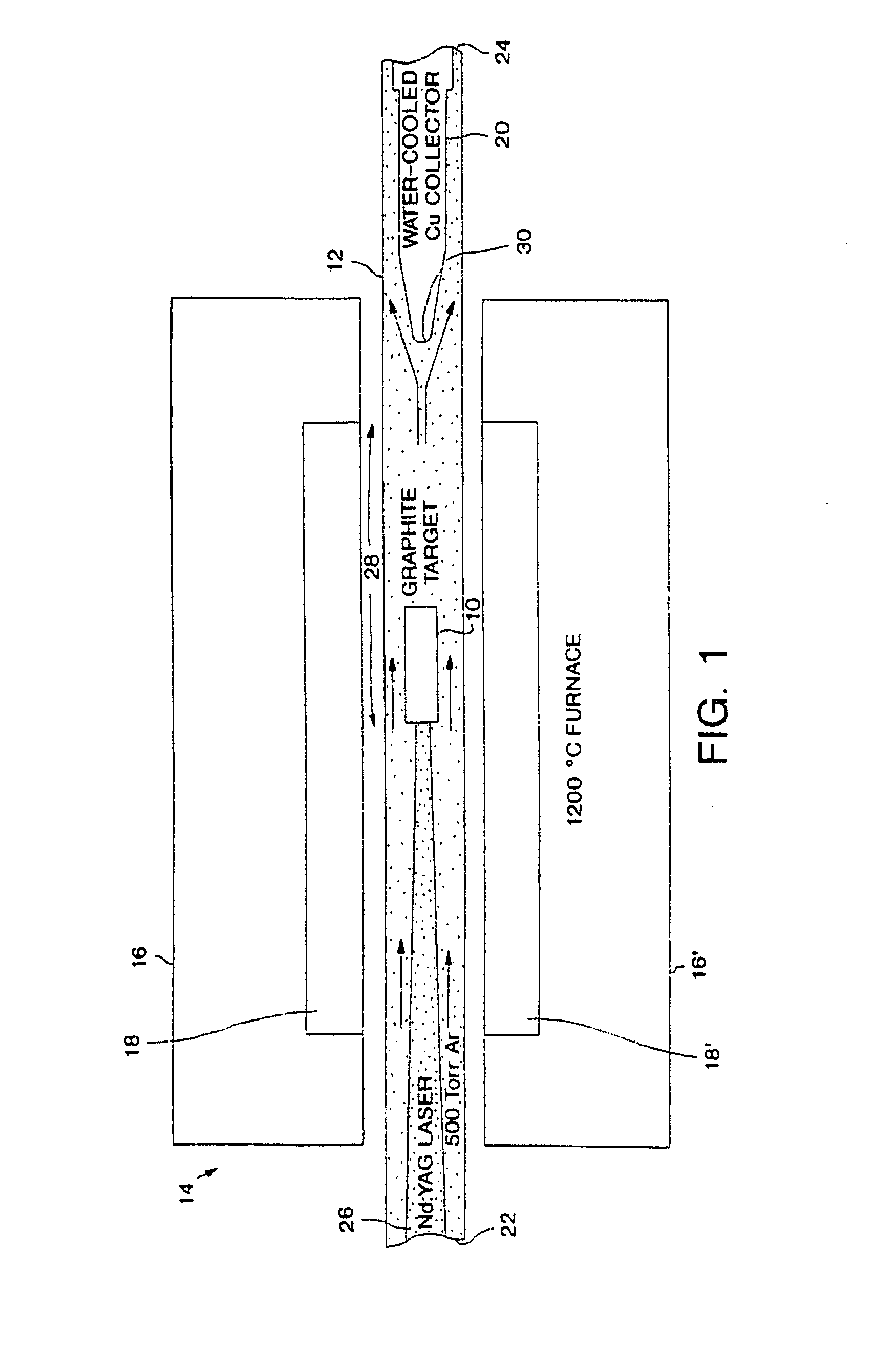
[0264] The oven laser-vaporization apparatus described in FIG. 1 and also described by Haufler et al., “Carbon Arc Generation of C60” Mat. Res. Soc. Symp. Proc., Vol. 206, p. 627 (1991) and by U.S. Pat. No. 5,300,203 was utilized. An Nd:YAG laser was used to produce a scanning laser beam controlled by a motor-driven total reflector that was focused to a 6 to 7 mm diameter spot onto a metal-graphite composite target mounted in a quartz tube. The laser beam scans across the target's surface under computer control to maintain a smooth, uniform face on the target. The laser was set to deliver a 0.532 micron wavelength pulsed beam at 300 milliJoules per pulse. The pulse rate was 10 hertz and the pulse duration was 10 nanoseconds (ns).

[0265] The target was supported by graphite poles in a 1-inch quartz tube initially evacuated to 10 mTorr, and then filled with 500 Torr, argon flowing at 50 standard cubic centimeters per second (sccm). Given the diameter of the qua...

example 2

Laser-Vaporization to Produce Longer Single-Wall Carbon Nanotubes

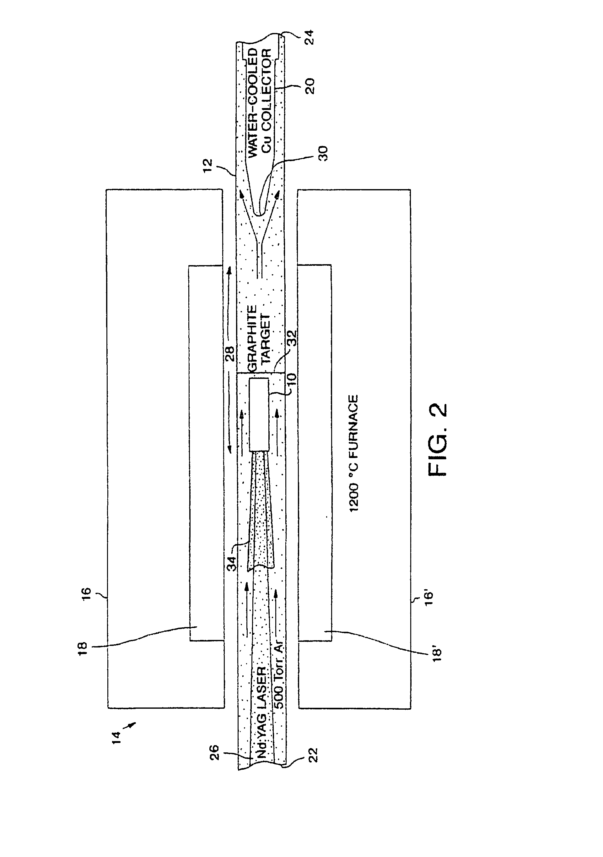
[0273] In this example, a laser vaporization apparatus similar to that described by FIG. 1 is used to produce longer single-wall carbon nanotubes. The laser vaporization apparatus was modified to include a tungsten wire strung across the diameter of a quartz tube mounted in an oven. The tungsten wire was placed downstream of the target so that the wire was 1 to 3 cm downstream from the downstream side of the target (13 to 15 cm downstream from the surface of the target being vaporized). Argon at 500 Torr, was passed through the quartz tube at a flow rate equivalent to a linear velocity in the quartz tube of about 1 cm / sec. The oven was maintained at 1200° C. and Group VII transition metals were combined at 1 to 3 atom % with carbon to make the target.

[0274] The pulsed laser was operated as in Example 1 for 10 to 20 minutes. Eventually, a teal drop shaped deposit formed on the tungsten wire, with portions growing to l...

example 3

Two Laser Vaporization

[0275] Graphite rods were prepared as described in Example 1 using graphite, graphite cement and 1.2 atom % of a mixture of 50 atom % cobalt powder and 50 atom % nickel powder. The graphite rods were pressed into shape and then formed into targets as described in Example 1. The graphite rods were then installed as targets in an apparatus as diagramed in FIG. 2. except tungsten wire 32 was not used. A quartz tube holding the graphite rod targets was placed in an oven heated to 1200° C. Argon gas which had been catalytically purified to remove water vapor and oxygen was passed through the quartz tube at a pressure of about 500 Torr and a flow rate of about 50 sccm although flow rates in the range of about 1 to 500 seem (standard cubic centimeters per minute), preferably 10 to 100 sccm are also useful for a 1 inch diameter flow tube. The first laser was set to deliver a 0.532 micron wavelength pulsed beam at 250 mJ per pulse. The pulse rate was 10 Hz and the puls...


PUM

PropertyMeasurementUnit
lengthaaaaaaaaaa
lengthaaaaaaaaaa
lengthsaaaaaaaaaa

Abstract

This invention relates generally to a fullerene nanotube composition. The fullerene nanotubes may be in the form of a felt, such as a bucky paper. Optionally, the fullerene nanotubes may be derivatized with one or more functional groups. Devices employing the fullerene nanotubes of this invention are also disclosed.

Description

RELATED APPLICATIONS [0001] This Application is a continuation of and claims priority to U.S. patent application Ser. No. 11 / 507,971, filed Aug. 22, 2006, presently pending, entitled “FULLERENE NANOTUBE COMPOSITIONS;” which is a divisional of prior U.S. patent application Ser. No. 10 / 033,470, filed Dec. 28, 2001, (issued as U.S. Pat. No. 7,105,596 on Sep. 12, 2006): which is a divisional of U.S. patent application Ser. No. 09 / 380,545, filed on Dec. 22, 1999. (issued as U.S. Pat. No. 6,683,783 on Jan. 27, 2004); which is the 35 U.S.C. §371 National Stage Application of International Application Number PCT / US98 / 04513 filed Mar. 6, 1998; which designated the United States claiming priority to: Provisional U.S. Patent Application Ser. No. 60 / 067,325 filed on Dec. 5, 1997; Provisional U.S. Patent Application Ser. No. 60 / 064,531, filed on Nov. 5, 1997; Provisional U.S. Patent Application Ser. No. 60 / 063,675, filed on Oct. 29, 1997; Provisional U.S. Patent Application Ser. No. 60 / 055,037, ...

Claims


Application Information

Patent Timeline
Patent Type & Authority Applications(United States)
IPC IPC(8): C01B31/00C07C21/00C07C211/00C07C221/00C07C321/00C07C33/00C07K5/06C07K5/08C07K5/10C07K7/06
CPCB82Y10/00B82Y30/00B82Y40/00C01B31/0213C01B31/0233G11C2213/71D01F9/12D01F9/127G11C13/025G11C2213/16C01B2202/02C01B32/162C01B32/154
Inventor SMALLEY, RICHARD E.COLBERT, DANIEL T.DAI, HONGJIELIU, JIERINZLER, ANDREW G.HAFNER, JASON H.SMITH, KENNETH A.GUO, TINGNIKOLAEV, PAVELTHESS, ANDREAS
Owner RICE UNIV
Why Eureka
Try Eureka