Photomask Blank and Photomask
a technology of photomask and blank, applied in the field of photomask blank and photomask, can solve the problems of preventing effective pattern transfer, reducing the application range of photomask, so as to achieve high light shielding property and chemical stability, and high etching processability.
- Summary
- Abstract
- Description
- Claims
- Application Information
AI Technical Summary
Benefits of technology
Problems solved by technology
Method used
Image
Examples
example
[0070] Examples and Comparative Examples are given below for illustrating the invention although the invention is not limited thereto.
examples 6-12
[0083] Photomask blanks (binary mask blanks) having a light-shielding film and an antireflective film deposited on a substrate were prepared by the following procedure.
[0084] Antireflective Film of Molybdenum Silicide Compound (Examples 6-9)
[0085] First, a light-shielding film (Si:Mo=9:1 in atomic ratio) having a thickness of 25 nm was deposited under the same conditions as in Example 1.
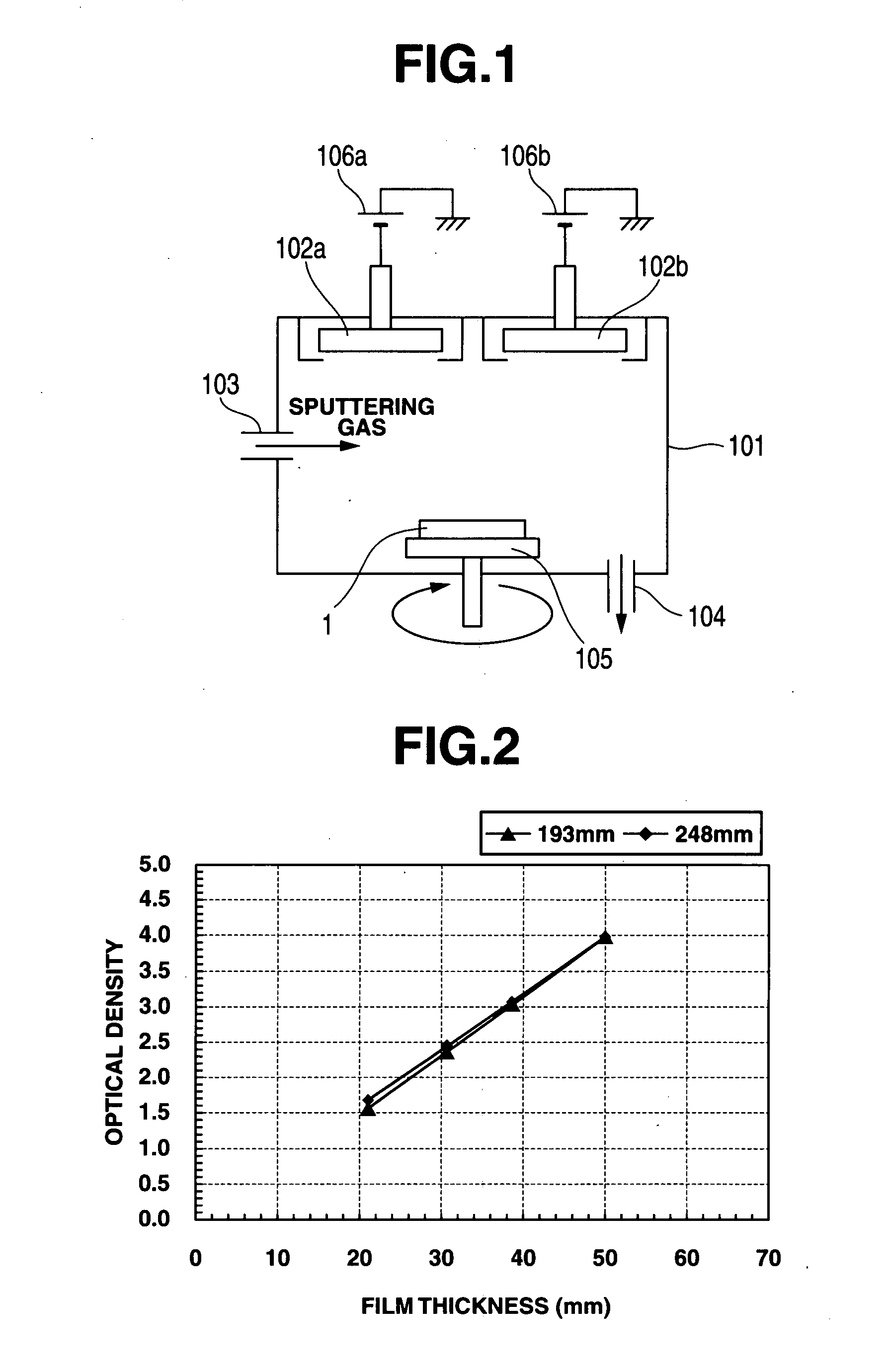
[0086] Next, using a DC sputtering apparatus having two targets as shown in FIG. 1, an antireflective film of molybdenum silicide nitride was deposited on the light-shielding film. Sputtering gases, Ar gas at a flow rate of 5 sccm, N2 gas at 50 sccm, and O2 gas at 0.2 sccm were introduced so as to establish a gas pressure of 0.1 Pa in the sputtering chamber. Two targets were used herein: a Mo target as the transition metal source and a Si (single crystal) target as the silicon source. Discharge powers of 150 W and 850 W were fed to the Mo and Si targets, respectively, while the substrate was rotat...
example 13
[0100] A halftone phase shift mask blank was fabricated and then processed into a halftone phase shift mask as follows.
[0101] At the start, a first layer of 10 nm thick was deposited on a quartz substrate of 6 inch square by a sputtering deposition process, specifically by using a MoZrSi4 sintered body and a Si single crystal as sputtering targets, feeding a discharge power of 560 W and 1,000 W to the MoZrSi4 and Si targets, respectively, and rotating the substrate at 30 rpm. During the process, a gas mixture of 8 sccm of Ar, 20 sccm of N2, and 5 sccm of O2 was introduced as the sputtering gas. The gas pressure during sputtering was set at 0.15 Pa.
[0102] Then, a second layer of 40 nm thick as shown in Table 1 was deposited while changing the discharge powers so as to apply 430 W to the MoZrSi4 target and 1,000 W to the Si target, changing the sputtering gas to a gas mixture of 15 sccm of Ar, 100 sccm of N2, and 1 sccm Of O2, rotating the substrate at 30 rpm, and setting a gas pres...
PUM
| Property | Measurement | Unit |
|---|---|---|
| molar ratio | aaaaa | aaaaa |
| thickness | aaaaa | aaaaa |
| thickness | aaaaa | aaaaa |
Abstract
Description
Claims
Application Information
 - R&D
- Intellectual Property
- Life Sciences
- Materials
- Tech Scout
- Unparalleled Data Quality
- Higher Quality Content
- 60% Fewer Hallucinations
Browse by: Latest US Patents, China's latest patents, Technical Efficacy Thesaurus, Application Domain, Technology Topic, Popular Technical Reports.
© 2025 PatSnap. All rights reserved.Legal|Privacy policy|Modern Slavery Act Transparency Statement|Sitemap|About US| Contact US: help@patsnap.com


