
Motor vehicle battery disconnect circuit having electronic disconnects

a technology of electronic disconnects and motor vehicles, which is applied in the direction of safety/protection circuits, process and machine control, instruments, etc., can solve the problems of poorly suited to interfacing with vehicle electrical systems and inability to operate vehicles

Inactive Publication Date: 2008-04-03
INT TRUCK INTPROP LLC
View PDF7 Cites 50 Cited by
  • Summary
  • Abstract
  • Description
  • Claims
  • Application Information

AI Technical Summary

Benefits of technology

[0008]The present invention is believed to represent an advance in motor vehicle electrical system technology through employing known solid-state devices in a unique way to create an electronic battery disconnect switch module that provides the benefits of solid-state construction and that enables versatile interfacing with a vehicle's electrical system, a capability apparently previously unavailable with electromechanical battery disconnect switches.
[0011]Vehicle Electrical System Protection is intended to protect the entire electrical system of the vehicle and all electrical circuits / components on the vehicle from “reverse battery” and “double battery” jump-start conditions.
[0015]The use of high-current, high-side semiconductor switches as the disconnect elements, with appropriate cooling techniques for solid-state devices that carry large electrical currents, can improve quality, reliability, and life expectancy of battery disconnect switches while at the same time providing additional diagnostic and protection features to vehicle electrical system. Improved quality, reliability, and life expectancy are achieved through a combination of the low “on resistance” of the semiconductor switches and effective control of their operating temperature.
[0016]Through the four feature groups described above, the invention is capable of measuring and reporting net battery current, battery charge current, and net battery voltage. An additional advantage will be the ability to detect and protect the vehicle batteries from excess drain. Once the battery drain threshold has been reached, the switches will shut off current to the current-draining electrical loads automatically to ensure enough residual battery charge capacity for engine cranking and starting. Still another advantage provided by the invention is protecting vehicle electrical systems from abnormal voltage events, such as a reverse battery connection and 24V jump-start applied to a 12V system. The invention can also monitor and log occurrence of such events for use in fleet management or maintenance.
[0026]Still another aspect of the invention relates to a method for protecting a battery bank having one or more D.C. storage batteries in an electrical system of an engine-powered land vehicle against loss of charge that renders the battery bank incapable of operating an electric starter motor that draws current from the battery bank to crank the engine at starting. The electrical system has electric load circuits that are fed from the battery bank through a disconnect switch module that comprises controlled conduction solid-state switch devices through which current can bi-directionally flow between the battery bank and the electric load circuits.

Problems solved by technology

If the battery bank is allowed to drain to the point where it cannot deliver the large cranking current necessary for starting the engine, the vehicle cannot be operated.
The inherent nature of such a switch seems to render it poorly suited for interfacing with vehicle electrical systems that have become largely electronic over the past several decades.

Method used


Image

  • Motor vehicle battery disconnect circuit having electronic disconnects
  • Motor vehicle battery disconnect circuit having electronic disconnects
  • Motor vehicle battery disconnect circuit having electronic disconnects

Examples


Embodiment Construction

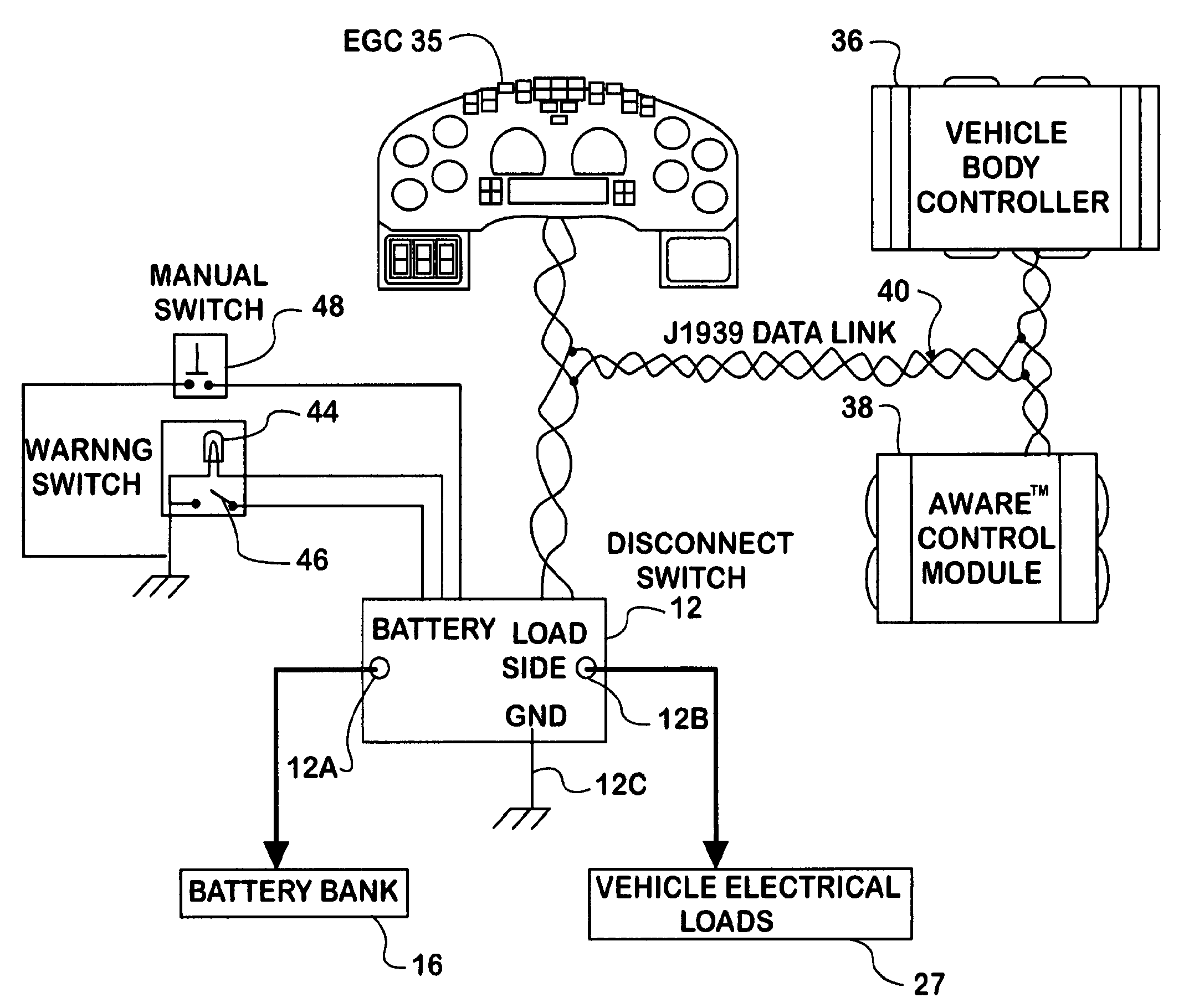
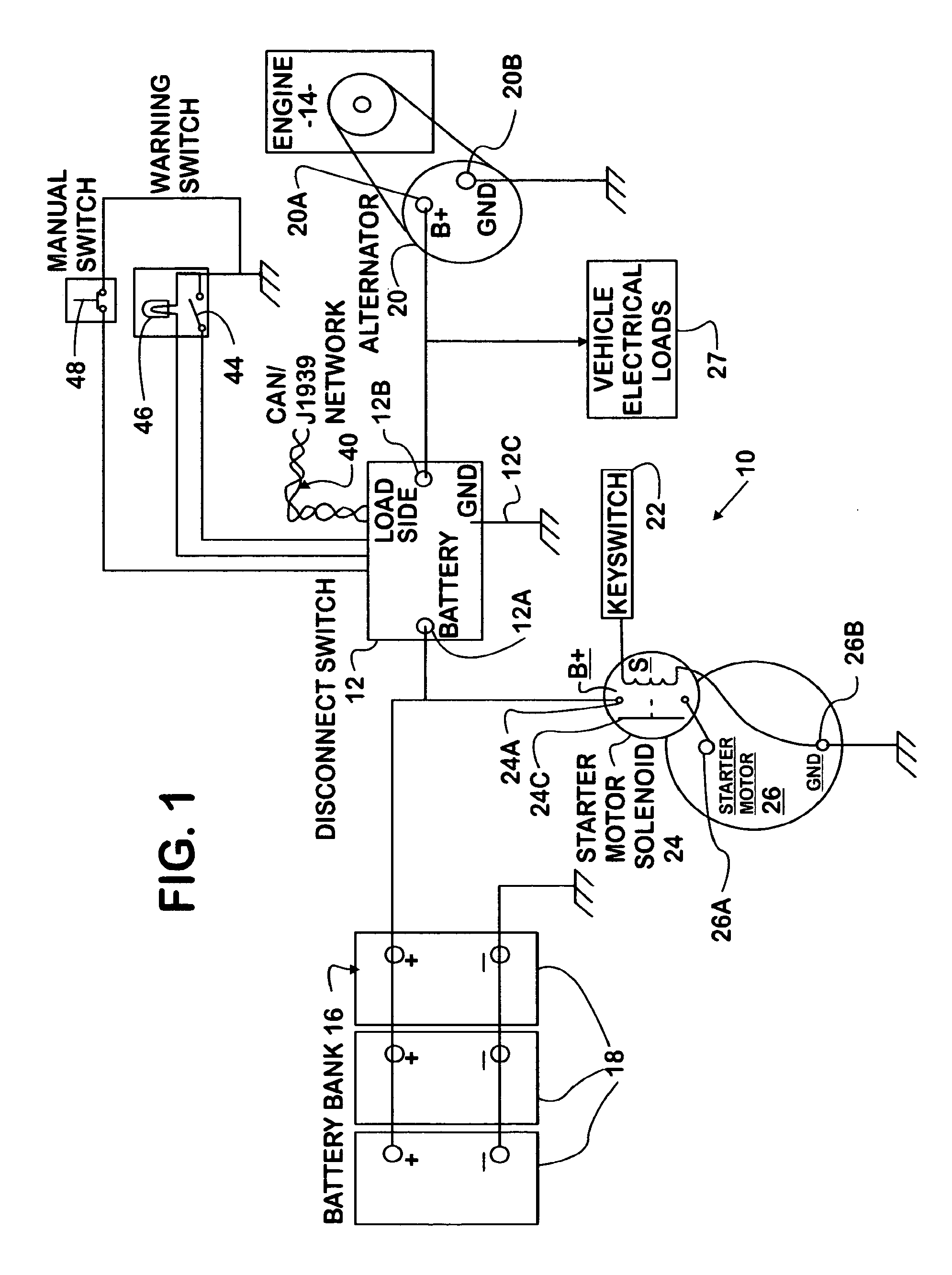
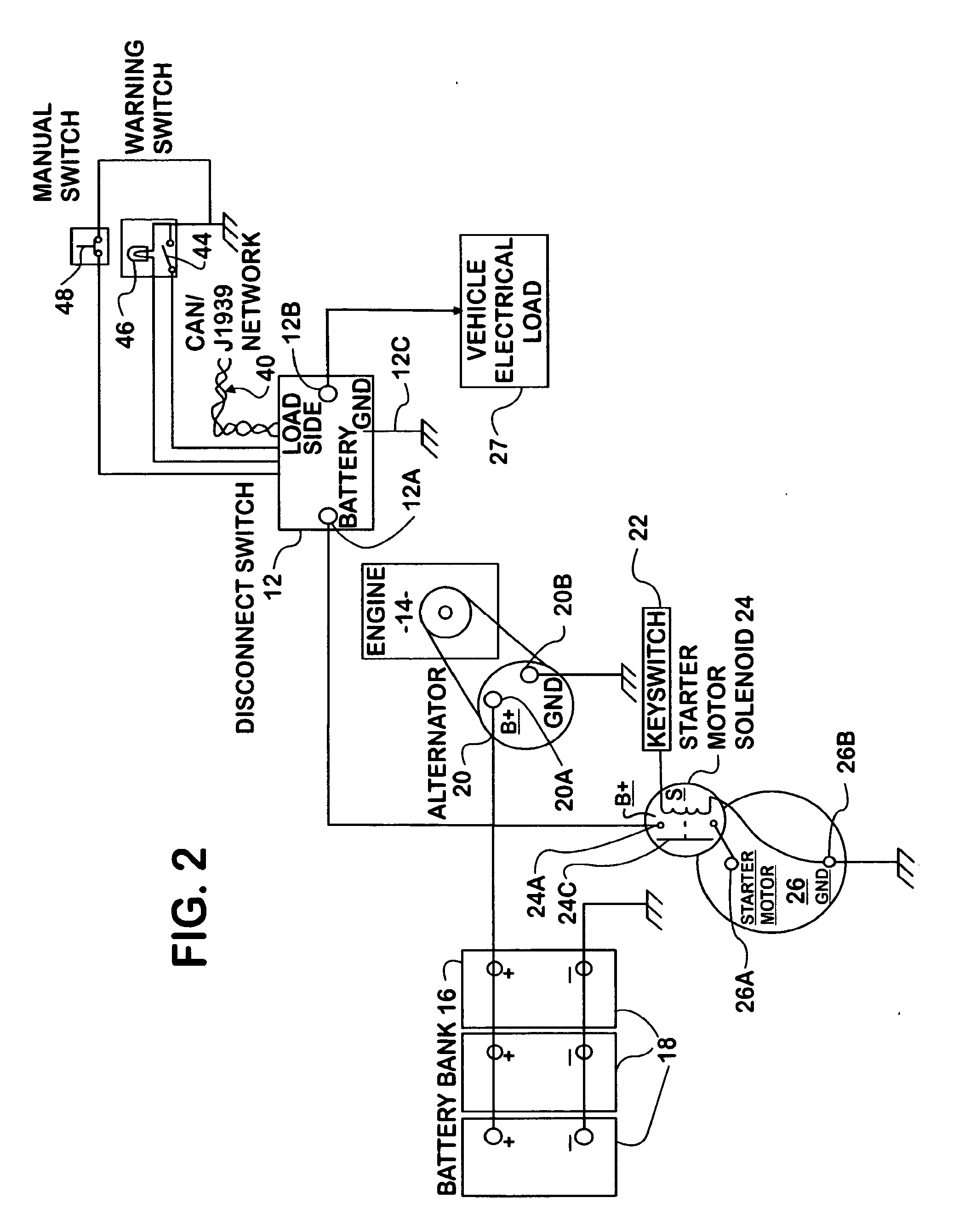
[0035]FIG. 1 shows a portion of a motor vehicle electrical system 10 that incorporates an electronic disconnect switch module 12 in accordance with principles of the present invention. While the particular example of motor vehicle shown is a truck powered by a diesel engine 14, principles of the invention can be applied to various vehicles where use of a disconnect switch is desired.

[0036]Electrical system 10 comprises a battery bank 16 containing one or more individual D.C. storage batteries 18. In a heavy truck powered by a diesel engine, battery bank 16 contains multiple batteries 18 ganged together as shown. When engine 14 is running, batteries 18 are kept charged by an engine-driven alternator 20 having positive and negative terminals 20A, 20B. Terminal 20A is connected to a terminal 12B on the load side of switch module 12, and the positive battery terminals are connected to a terminal 12A on the battery side of the switch module.

[0037]Running of the engine is under the contro...


PUM


Abstract

An electronic disconnect switch module (12) in a motor vehicle has one or more pairs of high-current, high-side solid state switch devices (30A, 30B, 32A, and 32B). The source terminal of one device of each pair is connected to vehicle load circuits (27), the source terminal of the other device of each pair is connected to the vehicle battery bank (16), and the drain terminals of the devices of each pair are connected in common. The module also has a microcontroller (34) that interfaces the switch devices with the vehicle electrical system. Four feature groups are provided: Vehicle Electrical System Protection, Battery Charge Control, Battery Disconnect, and Battery Monitoring.

Description

FIELD OF THE INVENTION[0001]This invention relates generally to electrical systems of motor vehicles. More particularly, the invention relates to battery disconnect devices and circuits for preventing battery drain that can occur, for example, when an engine-driven alternator does not operate for an extended period of time due to the engine being shut off and therefore is unable to maintain battery charge.BACKGROUND OF THE INVENTION[0002]Certain motor vehicles, heavy trucks that are powered by diesel engines for example, may be parked for extended periods of time. If the engine is allowed to keep running after a truck has been parked, the alternator should be effective to keep the truck's battery bank charged. If the engine is shut down, either intentionally by the driver, or automatically by a device such as an idle shutdown timer, while the circuits for electric devices remain on, the battery bank will begin to drain through those circuits. For example, an ignition switch will typ...

Claims


Application Information

Patent Timeline
IPC IPC(8): H02J7/00G05B9/02G06G7/70
CPCH02J7/1438H02J7/1461Y02T10/7005H02J2007/004H02J2007/0039H02J7/00304H02J7/00306Y02T10/70H02J7/00308
Inventor HOWELL, CLAYTON M.JERVIS, JOHN D.KELWASKI, H. EDWARD
Owner INT TRUCK INTPROP LLC
Learn More