
Pre-Clinical Animal Testing Method

a pre-clinical animal and testing method technology, applied in the field of pre-clinical animal testing methods, can solve the problems of inability to replace an implanted device, the conventional power supply of an implantable device may not be suitable for a variety of implanted devices, and the size of an implantable drug delivery device such as a pump may be too large for many locations in the body, so as to facilitate the disintegration of the implanted devi

Inactive Publication Date: 2008-04-03
MICROCHIPS INC
View PDF99 Cites 13 Cited by
  • Summary
  • Abstract
  • Description
  • Claims
  • Application Information

AI Technical Summary

Benefits of technology

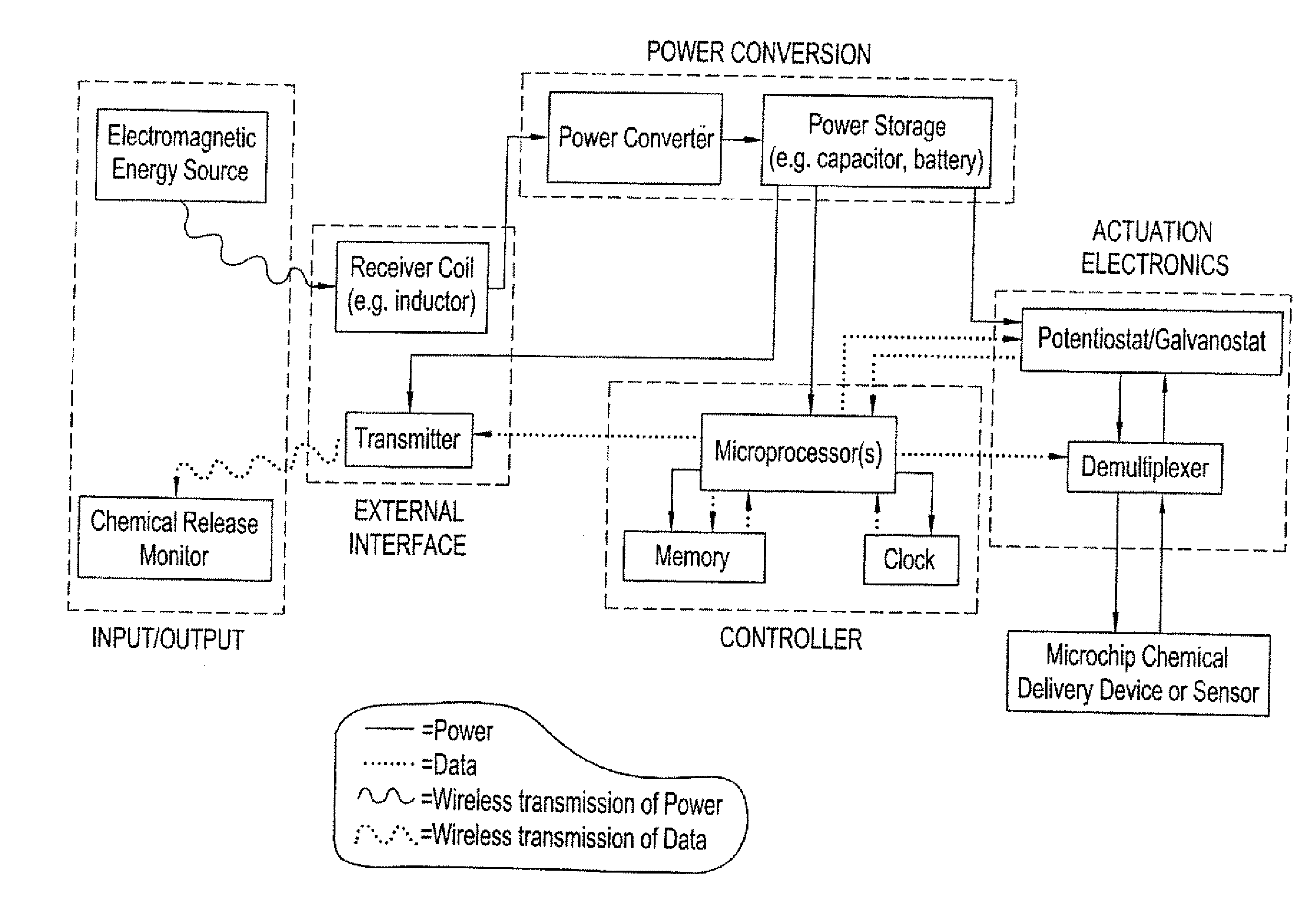
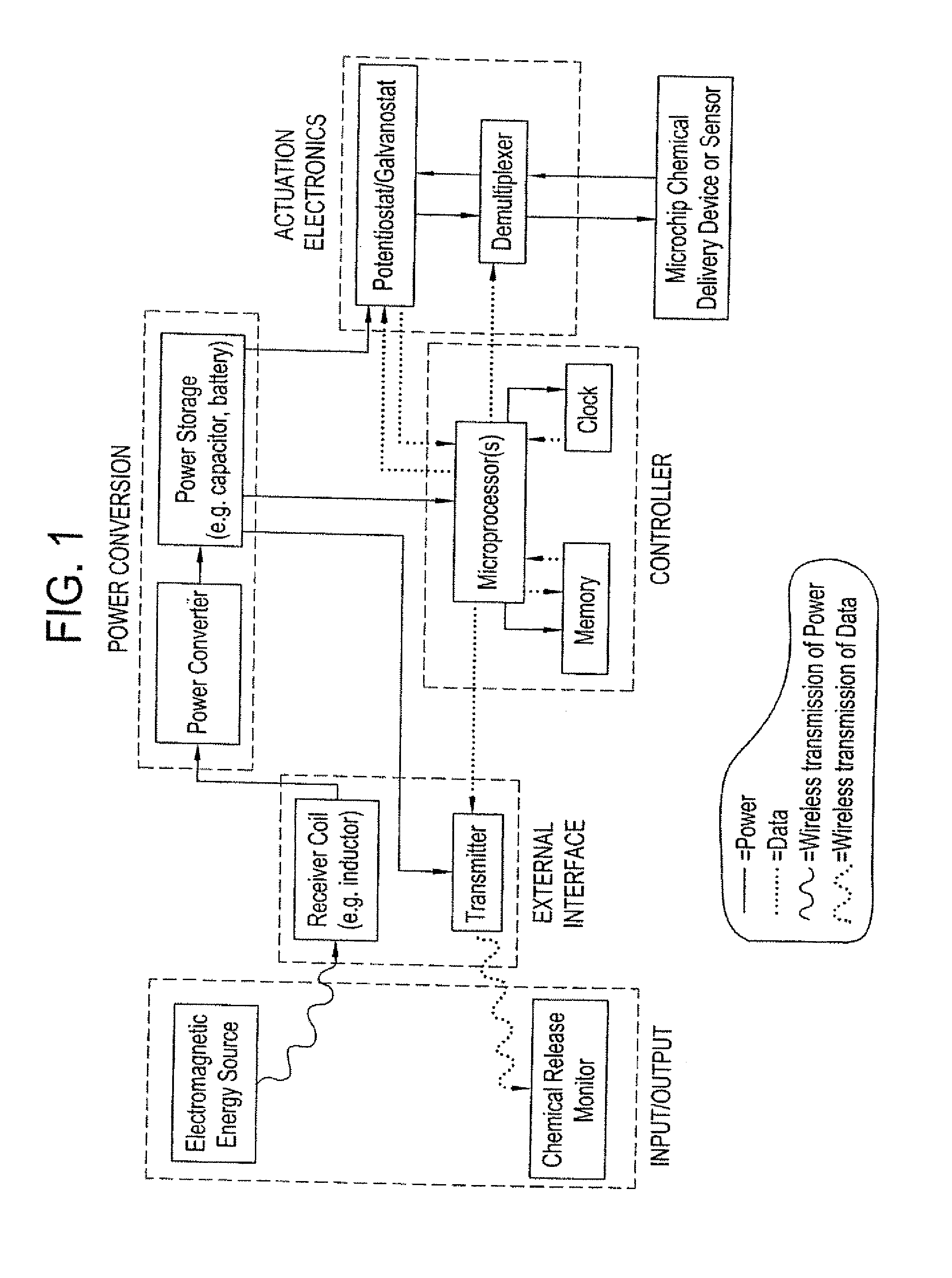
"The patent describes a system for controlled release or exposure of reservoir contents using a microchip device. The device contains multiple reservoirs that can release or expose the contents using a power source that is wirelessly received from a remote transmitter. The system does not require a power storage unit to be physically connected to the microchip device. The device can be implanted in the body of a human or animal, or used in various applications such as drug delivery or biological sensor detection. The system uses actuation electronics and a local controller to selectively open the reservoirs and a telemetry system to transfer data between the microchip device and a remote controller. The data transfer can be accomplished using a coil in the microchip device and a corresponding coil in the remote controller. The wireless transmission of power and data can be transmitted in the same signal and separated appropriately in the microchip device. The system can be used in various applications such as drug delivery or biological sensor detection."

Problems solved by technology

Currently available implantable drug delivery devices such as pumps may be too large for use in many of locations in the body.
If it cannot store all of the required power during the intended useful life of the microchip device, then the depleted battery must be replaced with a new battery.
However, such replacement typically is impractical or undesirable for an implanted device.
Furthermore, conventional means of powering an implantable device may be unsuitable for a variety of implanted devices, particularly for all possible implant locations.

Method used


Image

  • Pre-Clinical Animal Testing Method
  • Pre-Clinical Animal Testing Method
  • Pre-Clinical Animal Testing Method

Examples


example 1

Chemical Releasing Microchip with Electrochemical Actuation and RF Power Transmission

[0061] An electrochemically actuated microchip device having reservoirs covered by thin film gold reservoir caps can be fabricated using the processes described in U.S. Pat. No. 6,123,861. The reservoirs contain drug or other molecules for release. Application of an electric potential of approximately 1.0 volt (with respect to a saturated calomel reference electrode) in the presence of chloride ions would cause the reservoir caps to oxide and disintegrate, releasing the material stored in the reservoir. An on-demand power and control system would include an RF generating and a transmission source in an external controller unit. The microchip device would include a receiver coil (i.e. an inductor), an optional power converter (rectifier, regulator), a power storage unit (e.g., a capacitor, micro-battery), optional potentiostat or galvanostat circuitry (if electric potential or current modulation is ...

example 2

Microchip for the Selective Exposure of Reservoir Contents with Thermal Activation and RF Power Transmission

[0065] A microchip device similar to that described in Example 1 can be made with reservoirs containing catalysts for reactions and / or sensors for chemical and biological agent detection, wherein power transmitted by wireless methods can be used to open the reservoirs to selectively expose the contents. In this embodiment, electromagnetic energy is transmitted to a receiver coil located on or connected to the microchip device. The induced AC current can be rectified to DC current to charge a storage battery or capacitor, or sent directly to resistors located on, near, or inside the reservoirs that are to be opened. Current passing through the resistor will cause a temperature rise in the resistor and surrounding area. The rise in temperature can cause the reservoir cap material to disintegrate, melt, or phase change and selectively expose the sensor or catalyst. Alternatively...

example 3

Microchip for Release of Drug to the Eye Using Laser Actuation

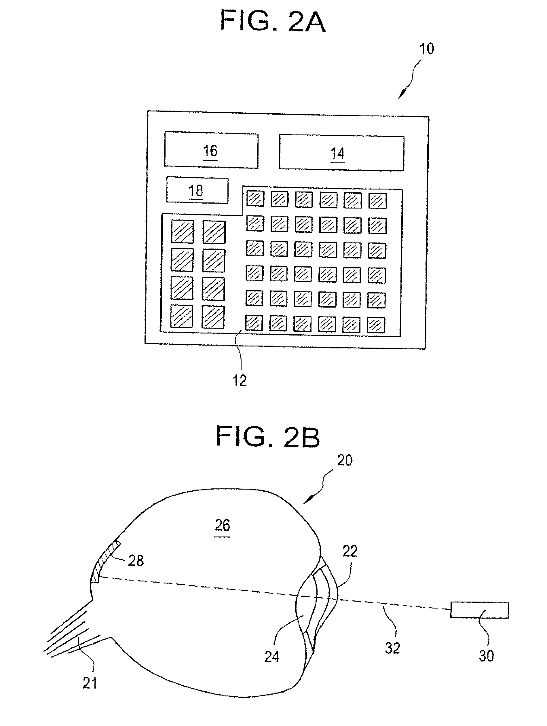
[0066] Lasers are used routinely in eye surgeries and other eye procedures for the treatment of conditions such as diabetic retinopathy, retinal detachments, age-related macular degeneration. Some conditions, notably macular degeneration, can be treated with periodic administration of medication delivered to the eye; however currently available means for doing so, such as injections, are difficult. To overcome such difficulties, an implantable microchip device can be provided to deliver doses of one or more types of medication to the eye on a periodic basis for an extended period of time. As the power requirements for electrochemically actuated silicon microchip devices with thin film gold reservoir caps are sufficiently small, the power can be wirelessly supplied, for example, via an ophthalmic laser. The ophthalmic laser also could be used to wirelessly communicate instructions to the implanted microchip device. Both p...


PUM


Abstract

Devices and methods are provided for wirelessly powering and / or communicating with implanted medical devices used for the controlled exposure and release of reservoir contents, such as drugs or sensors. The device may include a substrate having a plurality of reservoirs containing reservoir contents for release or exposure; and a rechargeable or on-demand power source comprising a local component which can wirelessly receive power from a remote transmitter wherein the received power can be used, directly or following transduction, to activate the release or exposure of the reservoir contents.

Description

CROSS-REFERENCE TO RELATED APPLICATIONS [0001] This is a divisional of U.S. application Ser. No. 09 / 975,672, filed Oct. 10, 2001, now U.S. Pat. No. 7,226,442, which claims priority benefit of U.S. Provisional Application No. 60 / 239,222, filed Oct. 10, 2000.BACKGROUND OF THE INVENTION [0002] This invention relates to miniaturized devices for the controlled exposure or release of molecules such as drugs and / or secondary devices such as sensors. [0003] Microchip devices for chemical and drug delivery and for controlled exposure of reservoir contents have been described in detail in U.S. Pat. No. 5,797,898; U.S. Pat. No. 6,123,861; PCT WO 01 / 64344; and PCT WO 01 / 35928. One group of embodiments of these microchip devices provides active release or exposure of the contents of a reservoir in the substrate of the device. “Active” is used to refer to those embodiments in which release or exposure is initiated at a particular time by the application of a stimulus to the device or a portion of...

Claims


Application Information

Patent Timeline
Patent Type & Authority Applications(United States)
IPC IPC(8): A61D7/00A61B5/0402A61B5/0476A61K9/00A61K9/22A61M5/14
CPCA61B1/041A61B5/0402A61B5/0476A61B5/14539A61K9/0009A61K9/0051A61M2210/1042A61M5/14A61M5/14276A61M2205/0244A61M2205/3523A61M2210/0612A61K9/0097A61B5/318A61B5/369
Inventor SANTINI, JOHN T. JR.AUSIELLO, DENNIS
Owner MICROCHIPS INC
Learn More