

Zirconia-ceria-yttria-based mixed oxide and process for producing the same
a technology of zirconia and ceria, which is applied in the direction of physical/chemical process catalysts, metal/metal-oxide/metal-hydroxide catalysts, separation processes, etc., can solve the problems of affecting catalytic performance and affecting stability, and achieve stable crystal structure and improve heat resistance of specific surface area
- Summary
- Abstract
- Description
- Claims
- Application Information
AI Technical Summary
Benefits of technology
Problems solved by technology
Method used
Image


Examples
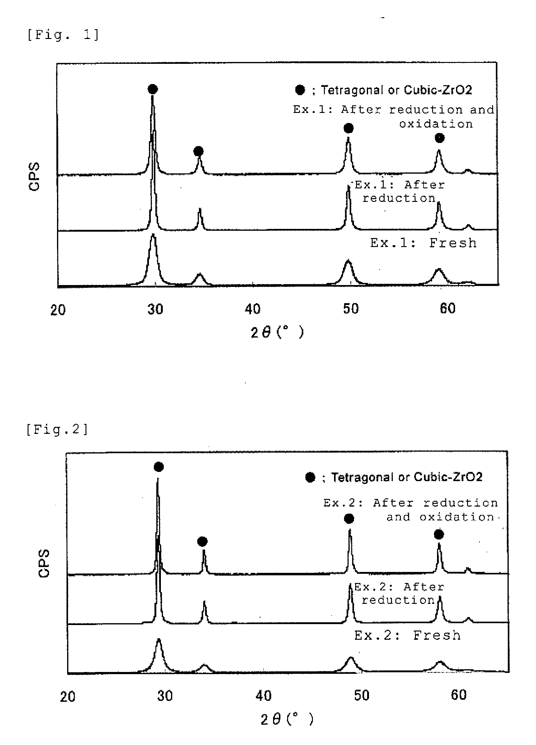
example 1
[0092] Zirconium oxychloride octahydrate in an amount of 70 g calculated as ZrO2 and an yttrium nitrate solution in an amount of 10 g calculated as Y2O3 were used to prepare a mixed solution. Using 35% hydrochloric acid and ion exchange water, the acid concentration and ZrO2 concentration in the mixed solution were adjusted to 0.67 N and 4 w / v %, respectively.
[0093] The obtained solution was heated to 70° C., a 5% sodium sulfate solution, adjusted with sodium hydroxide to a pH of 12.5, was added to the solution and heated to 95° C.
[0094] The mixed solution was maintained at the heated temperature for 15 minutes to obtain a basic zirconium sulfate-yttrium hydroxide-containing mixed slurry.
[0095] Subsequently, to the basic zirconium sulfate-yttrium hydroxide-containing mixed slurry, a cerium nitrate solution in an amount of 20 g calculated as CeO2 was added.
[0096] 500 g of a 25% sodium hydroxide aqueous solution was further added to obtain a zirconium hydroxide-cerium hydroxide-yt...
example 2
[0101] Zirconium oxychloride octahydrate in an amount of 45 g calculated as ZrO2, and an yttrium nitrate solution in an amount of 7 g calculated as Y2O3 were used to prepare a mixed solution. Using 35% hydrochloric acid and ion exchange water, the acid concentration and ZrO2 concentration in the mixed solution were adjusted to be 0.67 N and 4 w / v %, respectively.
[0102] To the obtained solution was added a 5% sodium sulfate solution adjusted with sodium hydroxide to a pH of 12.5 and heated to 95° C.
[0103] The mixed solution was maintained at the heated temperature for 15 minutes to obtain a basic zirconium sulfate-yttrium hydroxide-containing mixed slurry.
[0104] To the basic zirconium sulfate-yttrium hydroxide-containing mixed slurry, a cerium nitrate solution in an amount of 45 g calculated as CeO2, and a lanthanum nitrate in an amount of 3 g calculated as La2O3, were added.
[0105] 500 g of a 25% sodium hydroxide aqueous solution was further added to obtain a zirconium hydroxide-...
PUM
| Property | Measurement | Unit |
|---|---|---|
| specific surface area | aaaaa | aaaaa |
| oxidation-reduction potential | aaaaa | aaaaa |
| specific surface area | aaaaa | aaaaa |
Abstract
Description
Claims
Application Information