Sintered composite machine part and manufacturing method thereof

a composite machine part and composite technology, applied in the direction of reciprocating piston engines, machines/engines, engines without rotary main shafts, etc., can solve the problems of easy wear of the opposite piston and distributor of fluid, and achieve the effect of ensuring air tightness, excellent sliding properties, and efficient manufacturing of sintered composite machine parts

Active Publication Date: 2008-05-15
HITACHI POWDERED METALS COMPANY
View PDF8 Cites 10 Cited by
  • Summary
  • Abstract
  • Description
  • Claims
  • Application Information

AI Technical Summary

Benefits of technology

[0013]In accordance with the construction described above, a main body portion requiring strength and a sliding portion having proper hardness and durability are formed integrally, and a composite machine part preferable as a cylinder block of piston pump or piston motor, etc. is hence provided by making use of a method of powder metallurgy, so that an excellent sliding property is exhibited without damaging the opposite members when sliding.
[0014]Moreover, it is possible to manufacture a sintered composite machine part efficiently that a main body portion of sintered porous iron alloy material and a sliding portion of sintered porous copper alloy material are formed integrally by utilizing diffused junction. Airtightness is assured by sealing the pores of the main body portion by steam process, and a sintered composite machi

Problems solved by technology

However, the opposite members such as piston and distrib

Method used


Image

  • Sintered composite machine part and manufacturing method thereof
  • Sintered composite machine part and manufacturing method thereof
  • Sintered composite machine part and manufacturing method thereof

Examples


examples

[0051]The cylinder block was manufactured in the following procedure, and the state of diffused junction of the main body and the sliding part was observed.

[0052](Raw Material Metal Powder)

[0053]Copper powder 1.5 mass %, graphite powder 1.0 mass %, zinc stearate powder 0.8 mass % as molding powder lubricant, and the balance iron powder were blended and mixed to prepare a raw material metal powder for main body.

[0054]A zinc stearate powder 0.8 mass % as molding powder lubricant was added and mixed in a copper alloy powder of tin 10 mass % and the balance copper and inevitable amount of impurities, to prepare a raw material metal powder for sliding part.

[0055](Preparation of Main Body 20A)

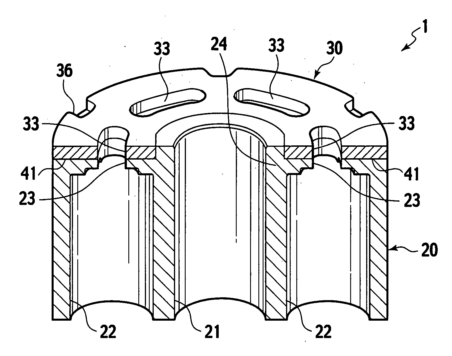
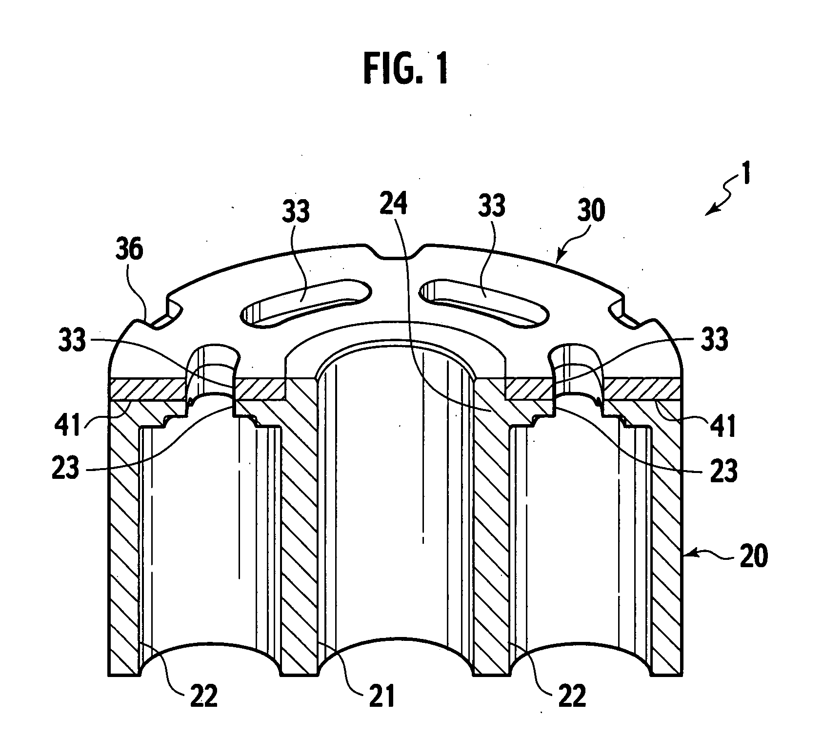
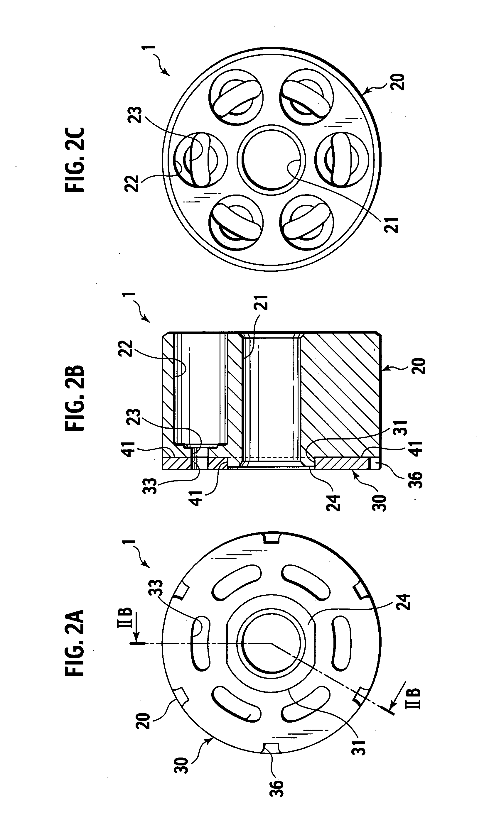
[0056]The material metal powder for main body was pressed to form a green compact for main body at compact density of 6.6 Mg / m3 in the form as shown in FIGS. 3A to 3C. This green compact for main body had outside diameter of 60 mm, length of 32 mm, pore size of 16 mm corresponding to the shaft hole 2...


PUM

PropertyMeasurementUnit
Temperatureaaaaaaaaaa

Abstract

Disclosed are a sintered composite machine part as a cylinder block for piston pumps or piston motors, and a manufacturing method thereof. The machine part has an air-tight main body of sintered porous iron alloy and having an iron oxide layer on the surface; and a sliding part of sintered porous copper alloy being bonded direct to the main body. The sliding part is to be slid in tight contact with a fluid supply/return device. The manufacturing is made by preparing a main body of sintered porous iron alloy and a green compact for sliding part from a raw material metal powder having a composition corresponding to the copper alloy; sintering the green compact for sliding part in contact with the main body to bond the sliding part to the main body by diffused junction; and subjecting the main body to steam treatment to provide an iron oxide layer.

Description

BACKGROUND OF THE INVENTION[0001]1. Field of the Invention[0002]The invention relates to a sintered composite machine part suited to a machine part required to have an airtightness and a locally high sliding property such as a cylinder block used in motion conversion between flowing fluid and rotary mechanism and its manufacturing method, and a cylinder block that can be manufactured by applying the same.[0003]2. Related Art[0004]A cylinder block is an element for composing a skew piston pump or skew piston motor, and is a rotating member having a plurality of cylinder holes with a bottom which are formed in parallel to a rotary shaft at equal intervals along a circumference concentric with the rotary shaft. By using the cylinder block in combination with a piston fitted into each cylinder hole, and a skew plate configured to rotate in connection with the reciprocal motion of the piston, motion can be converted between the flow of the fluid and the rotary motion of the shaft. Then, ...

Claims


Application Information

Patent Timeline
IPC IPC(8): F16J10/02B22F3/10B32B5/18
CPCB22F3/1146B22F5/008B22F7/002Y10T428/12042F16J15/0806F16J15/126B22F7/062B22F7/02B22F3/10
Inventor MOGAMI, MICHIHARU
Owner HITACHI POWDERED METALS COMPANY
Why Eureka
Try Eureka